Air Dryers—A-4400 Series Technical Bulletin 5
Capped High Pressure Connection
for High Pressure Riser
(Models with a Factory Mounted Air Purification System)
12-15/16
329
17-1/2
445
21-3/4
552
22-1/16
560
A-4412-1: A-4417-1 and A-4423-1:
12-5/8
321
23-3/16
589
A-4412-1:
18-1/16
459
A-4417-1 and
A-4423-1:
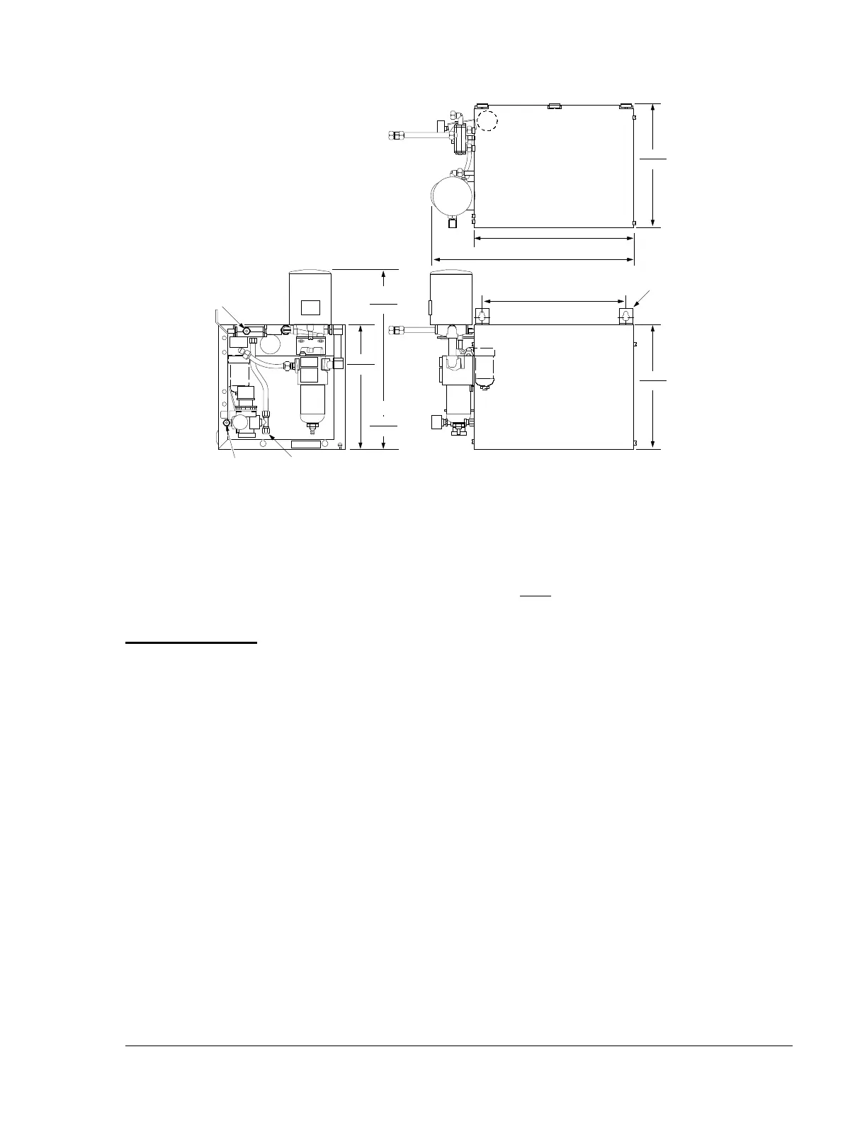
Note: The A-4400 requires 12 in. (305 mm)
top clearance and 12 in. clearance
on either end. When wall mounting
the A-4400, 10 in. (254 mm) bottom
clearance is recommended.
Also, attach the 3/8 in. discharge main
air line to the PRV before mounting.
In
Out
Key Slots
(Two Locations)
for 1/4 in. Bolts
(Field Furnished)
16
406
+
+
14-1/4
362
Figure 1: A-4400 Series Refrigerated Air Dryer Shown with
Optional Factory Mounted Air Purification System
The high pressure side of the compressed air line, after the compressor
tank, must be connected to the 3/8 in. compression inlet air connection.
On models with an optional factory mounted Air Purification System, this
inlet air connection is located on the service bypass valve. These models
also include a capped high pressure outlet connection (refer to Figure 1)
directly ahead of the PRV. To use this connection, remove the cap and
connect the high pressure outlet line to the 3/8 in. compression connection
provided. Check all air line connections for leakage.
Air
Connections
 Loading...