J500-42-00 2 I56-2198-003R
This device will not operate without electrical power. Fire situations may cause an interruption of power. The system safeguards should be dis-
cussed with your local fire protection specialist.
This device will not sense smoke unless the ventilation system is operating.
In order to function properly, this detector must be installed according to the instructions. Do not exceed the electrical or ambient specifications or the
detector will not function properly. This detector must be protected from the elements.
INSTALLATION SEQUENCE
Step 1. Verify duct air flow direction and velocity .....................................................................................................................................................2
Step 2. Drill the mounting holes ...............................................................................................................................................................................2
Step 2.1 Install the sampling tube for ducts less than 1
1
⁄ 2
feet wide .........................................................................................................................2
Step 3. Secure the detector housing to the duct ......................................................................................................................................................3
Step 4. Install the sampling tube for ducts greater than 1
1
⁄ 2
feet wide ...................................................................................................................
3
Step 4.1 Installation for ducts greater than 1
1
⁄ 2
feet but less than 8 feet wide ........................................................................................................
3
Step 4.2 Installation for ducts more than 8
feet wide ...............................................................................................................................................
4
Step 5. Install the filters ............................................................................................................................................................................................4
Step 6. Field wiring ...................................................................................................................................................................................................4
Step 7. Perform detector check ................................................................................................................................................................................5
Step 8. Install the cover ............................................................................................................................................................................................5
Step 9. Detector Maintenance and Test Procedures ................................................................................................................................................5
[1] Verify Duct Air Flow Direction And Velocity
The DH300PL duct smoke detector is designed to be used in air handling systems having air velocities of 100 to 4000 feet per minute. Be sure to
check engineering specifications to ensure that the air velocity in the duct falls within these parameters. If necessary, use a velocity meter to check
the air velocity in the duct.
[2] Drill The Mounting Holes
Remove the paper backing from the mounting template supplied. Affix the template to the duct at the desired mounting location. Make sure the tem-
plate lies flat and smooth on the duct. Center punch holes A and B. Drill the holes as indicated on the template.
[2.1] Sampling Tube Installation for Ducts Less Than 1
1
⁄2 Feet Wide (see Figure 2)
1. Remove the front cover.
2. Slide the plastic sampling tube into the housing bushing and extend it the full width of the duct.
3. Align the holes in the bushing with the holes in the sampling tube. Secure with the #8 self-tapping screw into the bottom of the permanent tube.
NOTE: For ducts greater than 1
1
⁄ 2 feet in width, refer to sections [4], [4.1] and [4.2].
[3] Secure The Detector Housing To The Duct
Slide the foam gaskets over the tube bushings as shown in Figure 3. Use the two 1
1
⁄ 4
″
long sheet metal screws to screw the detector housing to the
duct.
CAUTION: Do not overtighten the screws.
[4] Sampling Tube Installation for Ducts Greater Than 1
1
⁄ 2 Feet Wide
The sampling tube is identified by a series of air inlet holes on the tube. A plastic tube is
included for ducts up to 1
1
⁄ 2 feet wide. All other lengths must be purchased separately. Order
the correct length, as specified in Table 1, for width of the duct where it will be installed. It
is recommended that the sampling tube length extend at least
2
⁄ 3
across the duct width for
optimal performance. The exhaust tube is molded onto the base of the duct housing, and
the A2440-00 Exhaust Tube Extension is available as an accessory in those cases where
the molded exhaust port does not extend at least 2 inches into the duct.
The sampling tube is always installed with the air inlet holes facing into the air flow. To
assist proper installation, the tube’s mounting flange is marked with an arrow. Make sure
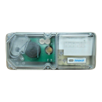
Figure 2. Plastic sampling tube
connected to duct smoke detector
H0110-00
 Loading...