56
Network Communications—N2 Communications Bus
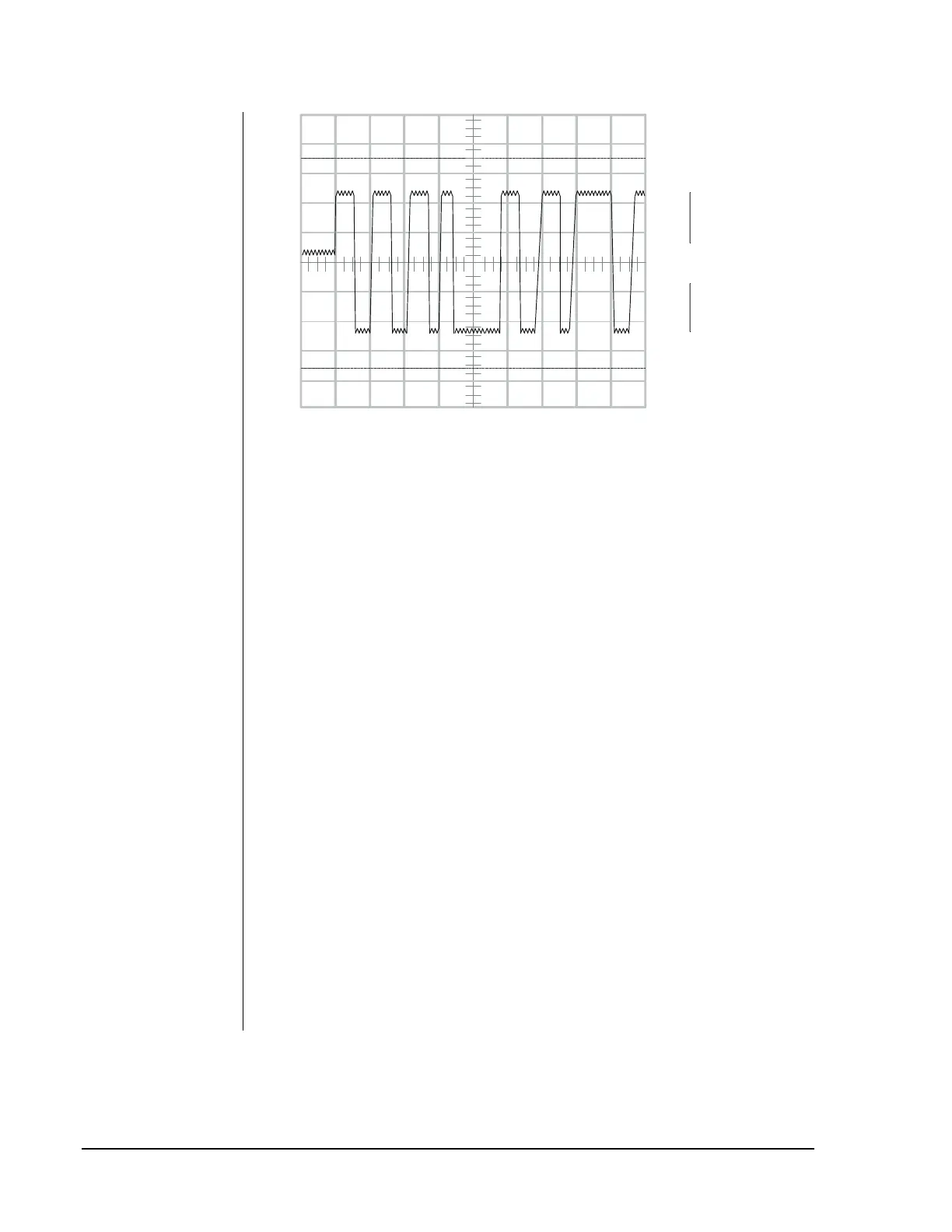
0 V -
Ch 1 = 2 V/div.
T/div 0.5 mS
3 to 10 V pp
(including +0.5 VDC Bias)
scopesg
Figure 33: N2Bus Signal as Measured with Oscilloscope
6.
Connect Channel B to the N2- wire and connect Channel A to the
N2+ wire. Connect the oscilloscope ground lead to the N2 Reference
wire.
7.
Compare the signal you measure with the waveform in Figure 33. They
should resemble the figure. A signal outside this range indicates that
the N2 Bus is not functioning properly.
Note: At the dead time between messages, you can measure the bias
voltage. In this figure, it is 0.5 VDC.
Factors that can cause improper signal levels are:
•
N2 Bus wires are not polarized correctly (i.e., wires are reversed).
•
N2 cable runs are too long.
•
24 AWG wire has breaks in it.
•
An ASC has malfunctioned.
•
N2 Bus is improperly terminated (e.g., EOL jumpers configured
improperly).
•
N2 Bus contains too many devices, loading down the bus.
•
N2 Bus wiring has T or Y connections installed.
•
Check all wiring and devices to pinpoint the problem. Replace parts if
necessary.