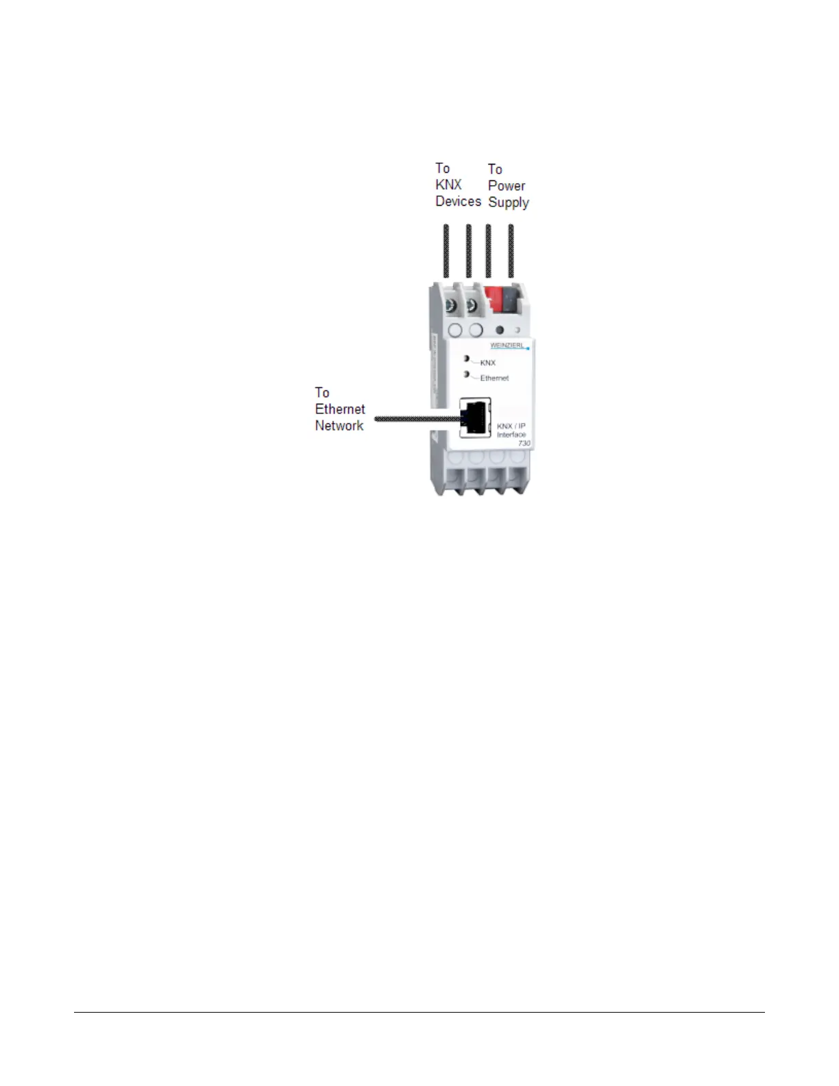
Figure 12: KNX/IP Interface Router
3. For a single KNX line, terminate the wires from the red and black terminals on the gateway to the devices. For
multiple KNX lines, terminate the wires from the red and black terminals on each gateway to the devices on the
same KNX line.
Note: Specific cabling can vary depending on the topology and site. See Wiring Rules for Networks and Field
Buses.
4. Terminate each KNX gateway to its own dedicated power supply on the KNX line.
Wiring Input and Output Terminals
NIE29 Series models support up to 33 hard-wired I/O points including:
• 7 BO points
• 4 CO points
• 4 analog output (AO) points
• 8 binary input (BI) points
• 10 Universal Input (UI) points
See Figure 13, Figure 14, and Terminal Wiring and Cable Length Guidelines Tables for more information.
The I/O points are designed for multiple types of input or output, and most of the points are configured in the CCT
software.
Terminal Functions, Ratings, Requirements, and Wiring Guidelines
Input and Output Wiring Guidelines
Table 12 provides information and guidelines about the functions, ratings, and requirements for the NIE input and
output terminals and references to guidelines for determining proper wire sizes and cable lengths.
12NIE29 Installation Instructions
 Loading...


