EasyManua.ls Logo

Johnson P4HUE30N13006 - User Manual

Johnson P4HUE30N13006
24 pages
Print Icon
To Next Page IconTo Next Page
Loading...
CONTENTS
GENERAL INFORMATION . . . . . . . . . . . . . . . . . . . . . . . . . . . . .3
UNIT INSTALLATION. . . . . . . . . . . . . . . . . . . . . . . . . . . . . . . . . .4
VENTING . . . . . . . . . . . . . . . . . . . . . . . . . . . . . . . . . . . . . . . . . . .7
DUCTWORK . . . . . . . . . . . . . . . . . . . . . . . . . . . . . . . . . . . . . . . .8
UPFLOW APPLICATIONS . . . . . . . . . . . . . . . . . . . . . . . . . . . . .8
HORIZONTAL APPLICATION . . . . . . . . . . . . . . . . . . . . . . . . . .9
GAS PIPING . . . . . . . . . . . . . . . . . . . . . . . . . . . . . . . . . . . . . . .10
ELECTRICAL POWER CONNECTION . . . . . . . . . . . . . . . . . . .11
ELECTRICAL CONTROL CONNECTIONS . . . . . . . . . . . . . . .12
SAFETY CONTROLS . . . . . . . . . . . . . . . . . . . . . . . . . . . . . . . .13
TSTART-UP AND ADJUSTMENTS . . . . . . . . . . . . . . . . . . . . .14
ACCESSORY CONNECTIONS . . . . . . . . . . . . . . . . . . . . . . . . .16
OPERATION AND MAINTENANCE . . . . . . . . . . . . . . . . . . . . .18
TROUBLESHOOTING . . . . . . . . . . . . . . . . . . . . . . . . . . . . . . . .20
HORIZONTAL (WITHOUT FILTER) . . . . . . . . . . . . . . . . . . . . .22
FILTER PERFORMANCE-PRESSURE DROP
INCHES W.C. . . . . . . . . . . . . . . . . . . . . . . . . . . . . . . . . . . . . . . .23
WIRING DIAGRAM . . . . . . . . . . . . . . . . . . . . . . . . . . . . . . . . . .24
INSTALLATION
INSTRUCTIONS
CAUTION: READ ALL SAFETY GUIDES BEFORE YOU
START TO INSTALL YOUR FURNACE.
SAVE THIS MANUAL
MULTI-POSITION
GAS-FIRED FURNACES
COMMERCIAL BELT DRIVE
UPFLOW / HORIZONTAL MODELS: P4HUE30N13006
130 MBH OUTPUT
035-17443-000 Rev. A (800)

Table of Contents

Question and Answer IconNeed help?

Do you have a question about the Johnson P4HUE30N13006 and is the answer not in the manual?

Summary

GENERAL INFORMATION AND INSTALLATION PREPARATION

Furnace Description, Inspection, and Safety Guidelines

Covers furnace description, inspection procedures, and general safety notes.

Installation Location Limits and Combustion Air

Details location restrictions, codes, and combustion air requirements.

Venting Procedures and Safety Checks

Explains venting methods, temperature limits, and safety check procedures.

GAS PIPING AND ELECTRICAL CONNECTIONS

Gas Piping Installation and Safety Precautions

Covers gas piping requirements, shutoff valves, pressure testing, and connections.

Electrical Power Connection Requirements

Details field wiring requirements for power supply and grounding.

Electrical Control Wiring and Thermostat Setup

Provides instructions for connecting thermostats and control circuits.

SAFETY CONTROLS AND START-UP PROCEDURES

Furnace Safety Control Systems Overview

Describes safety controls like blower door switch, rollout, pressure, and limit controls.

Ignition System Checkout and Gas Input Verification

Procedures for checking the ignition system and verifying gas input rate.

Gas Pressure and Temperature Rise Adjustments

Covers adjustment of manifold gas pressure and temperature rise.

OPERATION, MAINTENANCE, AND TROUBLESHOOTING

Furnace Operation Sequence and Maintenance

Details the heating cycle, blower operation, and general maintenance tasks.

Burner, Heat Exchanger, and Filter Servicing

Instructions for cleaning and servicing burners, heat exchangers, and filters.

Furnace Troubleshooting and Diagnostic Codes

Guides on identifying and resolving furnace issues using diagnostic codes.

Filter Performance and System Airflow Calculation

Explains how filter performance affects system airflow and how to calculate it.

Overview

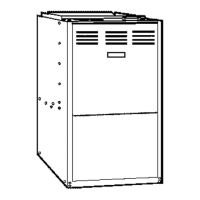
This manual describes a Multi-Position Gas-Fired Furnace from the Commercial Belt Drive series, specifically the P4HUE30N13006 model with a 130 MBH (thousand British Thermal Units per hour) output. It is designed for both upflow and horizontal installations.

Function Description

The furnace is a Category I gas-fired appliance suitable for residential and commercial applications. It features a fan-assisted combustion system that uses an integral mechanical means to draw combustion products through the combustion chamber and heat exchanger. The unit is designed for natural gas-fired operation but can be converted to propane (LP) using the INP0349 kit. Its primary function is to provide heating for a building by circulating heated air through a duct system. The control system incorporates a hot surface ignition system for reliable burner ignition and various safety controls to ensure safe operation.

Important Technical Specifications

  • Model: P4HUE30N13006
  • Output: 130 MBH
  • Input MBH: 160
  • AFUE (Annual Fuel Utilization Efficiency): 78%
  • Air Temperature Rise: 25-55°F
  • Max. Outlet Temperature: 150°F
  • Blower Motor HP: 1-1/2
  • Blower Motor Amps @230V: 10
  • Blower Dimensions: 12 x 15 inches
  • Total Unit Max. Amps: 15 (208/230 VAC only), 6 & 11 (115 and 208/230 VAC split), 27 (115 VAC only)
  • Overcurrent Protection Size: 20A (208/230 VAC only), 15A (115 and 208/230 VAC split), 30A (115 VAC only)
  • Min. Wire Size (AWG) @75 ft. One Way: 12 (208/230 VAC only), 12 (115 and 208/230 VAC split), 10 (115 VAC only)
  • Operating Gas Type: Natural Gas (convertible to Propane (LP) with kit INP0349)
  • Manifold Pressure (Natural Gas): 3.5" W.C.
  • Manifold Pressure (Propane LP): 10.0" W.C.
  • Inlet Gas Pressure Range (Natural Gas): 4.5" W.C. (Min) to 13.9" W.C. (Max)
  • Inlet Gas Pressure Range (Propane LP): 11" W.C. (Min) to 13.9" W.C. (Max)
  • Electrical Power Supply: Factory wired for 208/230 VAC, 1 phase, 60 Hertz. Blower motor circuit can be changed to 115 volts (standard 1-1/2 HP motor only) by revising internal motor connections.
  • Control Circuit: 115 volt power supply.
  • Minimum Clearances to Combustibles (Upflow/Horizontal): Top 1", Front 6", Rear 0", Left Side 0", Right Side 3", Flue 6", Floor/Bottom Combustible.
  • Minimum Clearances to Combustibles (Upflow/Horizontal B-Vent): Top 1", Front 3", Rear 0", Left Side 0", Right Side 0", Flue 1", Floor/Bottom Combustible.
  • Continuous Return Air Temperature: Must not be below 55°F (13°C).
  • High Altitude Derating: For installations above 2,000 feet, reduce input 4% for each 1,000 feet above sea level. Canadian installations must be derated 10% for elevations from 2,000 ft. to 4,500 ft. (Use 1PS0301 kit).

Usage Features

  • Multi-Position Installation: Can be installed in upflow or horizontal configurations. Horizontal installation allows airflow toward the left or right by laying the unit on the corresponding side panel.
  • Combustion Air Options: Can draw combustion air from an unconfined space, a confined space with openings to interior areas, or directly from outdoors via ducts to crawl or attic spaces.
  • Venting Options: Supports Category I vertical venting with B-vent or masonry chimney, and horizontal sidewall venting using an auxiliary power venter (Fields Controls Model SWG-4Y or Tjernlund Model GPAK-JT).
  • Ductwork Requirements: Requires a closed duct system with supply connected to the furnace outlet and return connected to the furnace inlet. Return air can enter through the bottom only, or a bottom and one side. Rear panel return is not allowed.
  • Filter Installation: All installations require a field-supplied filter located outside the furnace cabinet in a filter rack, duct system, or filter grille. High velocity filters are required for air velocities over 300 feet per minute.
  • Thermostat Compatibility: Compatible with field-supplied thermostats. Heat anticipator setting of 0.45 amps is recommended for mechanical thermostats.
  • Accessory Connections: Features dedicated 115 VAC terminals for electronic air cleaners (1.0 amp max) and humidifiers (1.0 amp max) that operate during circulating blower operation or heating, respectively.
  • Twinning Capability: Can be twinned with another furnace using the 2TC03700124 twinning kit and 2TS03700106 accessory sensor kit, requiring simultaneous blower operation.
  • Safety Controls:
    • Rollout Switch Controls: Manual reset controls on the burner assembly that de-energize the igniter and gas valve if burner compartment temperature exceeds set point.
    • Pressure Switch: Monitors flow through the furnace and venting system, de-energizing ignition control and gas valve if blockages or blower failure occur.
    • Limit Controls: Automatic reset high-temperature limit controls protect against overheating due to reduced airflow (e.g., dirty filter, blower motor malfunction).
    • Blower Door Safety Switch: An electrical interlock switch that interrupts 115 volt control power when the blower door panel is removed.
    • Control Circuit Fuse: A 3-amp ATO-3 automotive type fuse protects the 24 volt transformer from overloads.
  • Diagnostics: Built-in self-diagnostic capability with a blinking LED to indicate fault codes. Fault codes range from 1 to 11 flashes, with a "Steady On" state for specific issues. Includes a 60-minute automatic reset from lockout for certain operational faults.

Maintenance Features

  • Air Filters: Filters should be checked periodically for dirt accumulation and cleaned or replaced at least every three months. New construction installations require weekly checks for the first four weeks, then every three weeks.
  • Lubrication: Blower and venter motors are permanently lubricated and do not require periodic oiling.
  • Blower Care: The entire blower assembly should be inspected annually. If heavily coated with dust, the motor and wheel can be brushed and cleaned with a vacuum cleaner. Instructions for removing the blower assembly are provided.
  • Burner Cleaning: Main burners should be checked periodically for dirt accumulation. Cleaning involves removing the burner assembly and rinsing in hot water or using a vacuum cleaner.
  • Heat Exchanger Cleaning: If sooted, replacement is recommended due to cleaning difficulty. Instructions for accessing and cleaning the lower and upper heat exchanger sections are provided, involving removal of the burner assembly and venter motor assembly.
  • Start-up and Adjustments: Detailed procedures for initial start-up, ignition system checkout, checking gas input, adjusting manifold gas pressure, and adjusting temperature rise are included.
  • Fan-Off Control Settings: The fan-off delay is field adjustable from 60 to 180 seconds, with a factory setting of 120 seconds, to ensure adequate furnace cooling without blowing cold air.

Johnson P4HUE30N13006 Specifications

General IconGeneral
BrandJohnson
ModelP4HUE30N13006
CategoryFurnace
LanguageEnglish

Related product manuals