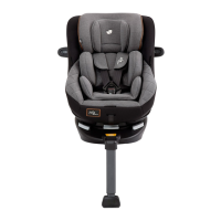
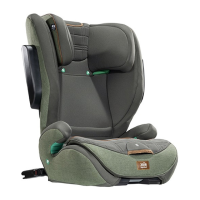
11 12
! There are 11 adjustable positions
for ISOFIX. Whilst depressing the
ISOFIX button
5
-1, pull out the
ISOFIX connector.
5
-2
! Make sure that both ISOFIX
connectors are securely attached
to their ISOFIX anchor points. The
colors of the indicators on both
ISOFIX connectors should be
completely green.
6
-1
! After successfully installing the
ISOFIX connectors, press the
ISOFIX adjustment buttons again
while pushing the seat back until it
comes in contact with the vehicle
seat back.
6
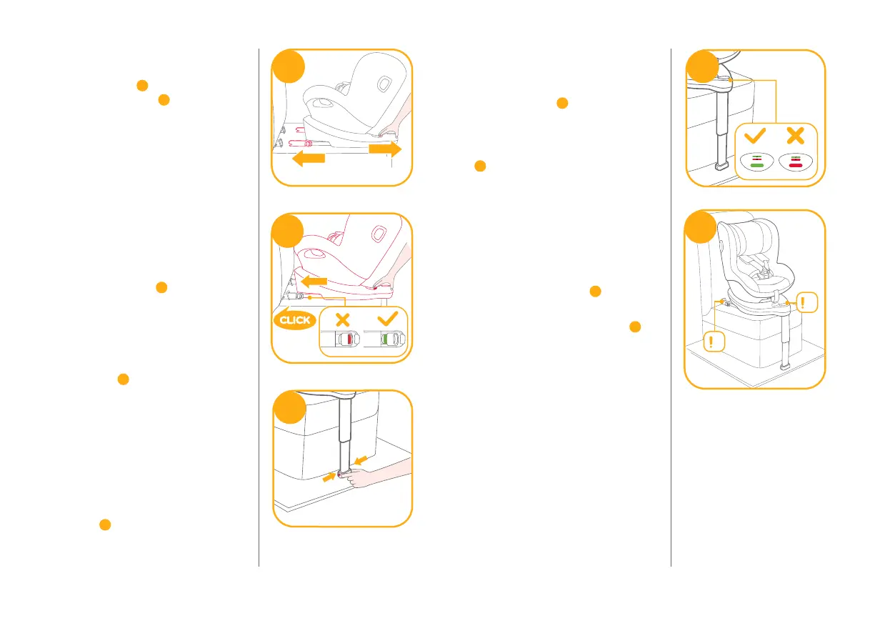
! After attaching the ISOFIX, pull the
load leg downward to floor. When
the load leg indicator shows green,
the load leg is installed correctly.
! Squeeze the load leg releasing
button, then adjust the load leg
length.
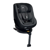
7
5
1
2
1
6
7
!
The load leg has 19 positions.
When the load leg indicator shows
red this means the load leg is in the
wrong position.
8
!
Make sure the load leg is in full
contact with the vehicle floor pan.
Red means it is installed incorrectly.
8
!
Check to make sure the base is
securely installed by pulling on
both ISOFIX connectors.
!
The ISOFIX connectors must be
attached and locked onto the
ISOFIX anchor points.
9
-1
!
The load leg must be installed
correctly with green indicator.
9
-2
8
9
1
2