This document is the Installation Manual for Jolywood N-type Mono-crystalline Double Glass Modules. It provides comprehensive guidelines for the installation, maintenance, and use of these photovoltaic (PV) modules.
Function Description:
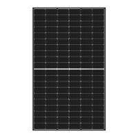
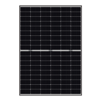
The Jolywood N-type Mono-crystalline Double Glass Modules are designed to convert sunlight into electricity, forming part of a solar photovoltaic system. These modules are intended for long-term use, with a projected lifespan of over 30 years under specified conditions. They are suitable for installation in various environments, including wet (coastal) areas and regions prone to sandstorms, and have been tested for resistance to ammonia. The modules can be installed either horizontally or vertically, with lateral installation recommended to minimize the impact of dust shading.
Important Technical Specifications:
- Module Types: The manual applies to standard components JW-D60N, JW-D72N, JW-HD120N/P, JW-HD144N/P, and JW-HD156N.
- Maximum System Voltage: According to the National Electrical Code, the maximum system voltage shall not exceed 1500V.
- Cables and Connectors: Each component features two standard 90°C blackout output cables with a plug-and-play connector on each terminal. These are DC copper cables with a cross-sectional area of four mm², rated voltage 1500V DC, insulation resistance up to 90°C, and are UV-resistant. All cables and connectors used in the DC system must have similar or higher parameters.
- Grounding: All component frames and mounting brackets must be properly grounded in accordance with the National Electrical Code. The grounding conductor can be copper, copper alloy, or other suitable electrical conductor. Grounding is achieved by continuously connecting the component frame and all metal structural members. The electrical contact is formed by penetrating the anodized coating of the aluminum frame and tightening the ground screw (with a star washer) to a torque of 25 lbf.in. A properly sized solid bare copper wire (AWG 6 to 12) should be used.
- Mechanical Load: The mechanical load (including snow and wind loads) depends on the installation method and must be calculated by a professional system designer based on actual and environmental conditions. The modules are not designed to withstand excessive force from thermal expansion of the support structure.
- Bolt Mounting (Conventional): For framed bifacial single-glass modules, mounting involves bolting to the support structure using holes on the back of the frame. Each module requires fastening at least at 4 points on two opposite sides. M8 x 1.25 (5/16") bolts and nuts with a yield strength of at least 450 MPa are recommended, with a torque of 16-20 Newton meters. All parts in contact with the frame should be stainless steel flat washers with a diameter of 16 mm and a minimum thickness of 1.6mm.
- Clamp Mounting (Frameless Bifacial Single-Glass Modules):
- JW-D60N / JW-HD120N/P (Parallel Long Side): Four-point long-side installation with C-shaped steel parallel long side. Clamp height 30mm, width 40-50mm. A=350±20mm. Load Pressure: front≤2400pa, back≤2400pa.
- JW-D60N / JW-HD120N/P (Vertical Long Side): Four-point long-side installation with C-shaped steel vertical long side. Clamp height 30mm, width 40-50mm. A=350±20mm. Load Pressure: front≤5400pa, back≤2400pa.
- JW-D72N / JW-HD144N/P (Parallel Long Side): Four-point long-side installation with C-shaped steel parallel long side. Clamp height 30mm, width 40-50mm. A=450±20mm. Load Pressure: front≤2400pa, back≤2400pa.
- JW-D72N / JW-HD144N/P (Vertical Long Side): Six-point long-side installation with C-shaped steel vertical long side. Clamp height 30mm, width 40-50mm. A=450±20mm. B=1008mm (intermediate) for JW-D72N, B is 100mm from the center for JW-HD144N/P. Load Pressure: front≤5400pa, back≤2400pa.
- JW-HD156N (Parallel Long Side): Six-point long-side installation with C-shaped steel parallel long side. Clamp height 30mm, width 40-50mm. A=450±20mm. B=1090mm (intermediate). Load Pressure: front≤2400pa, back≤2400pa.
- JW-HD156N (Vertical Long Side): Six-point long-side installation with C-shaped steel vertical long side. Clamp height 30mm, width 40-50mm. A=450±20mm. B is 100mm from the center. C-shaped steel without bolts is installed perpendicular to the long side. Load Pressure: front≤5400pa, back≤2400pa.
- Fuse Rating: The maximum fuse rating connected in series with the array is typically 20A, but specific ratings are on the product label and data sheet. This rating corresponds to the maximum reverse current the component can withstand.
Usage Features:
- Safety First: Users must read and understand all safety rules before installation, wiring, operation, or maintenance. Direct contact with live parts can be fatal.
- Qualified Personnel: Installation and maintenance must be performed by qualified personnel with specialized knowledge. Unauthorized personnel should not touch modules or access installation/storage areas.
- Environmental Conditions: Do not install or operate modules during wet or windy weather. Work in a dry environment with dry tools. Keep connectors dry and clean to prevent electric shock.
- Handling: Avoid damaging, scratching, or striking modules. Do not use paint or adhesive. Do not drop modules or place heavy/sharp objects on them. Do not lift modules by the terminal box or lead wires. Use both hands to carry modules.
- Unpacking: Unpacking requires two or more people. Modules should be placed horizontally and stably. Wear protective gloves to avoid injury and fingerprints.
- Storage: Modules should be stored in their original boxes. If stored outdoors temporarily, cover them and ensure the glass faces down to prevent water entry and connector damage. Do not stack more than two layers of double glass modules.
- Wiring: Connect modules in series to increase voltage (positive to negative). Connect in parallel to increase current (positive to positive, negative to negative). Ensure correct polarity to prevent bypass diode damage. All wiring must comply with the National Electrical Code.
- Bypass Diodes: Jolywood PV module junction boxes are equipped with bypass diodes to minimize component heating and current loss.
Maintenance Features:
- Regular Inspection: PV array components should be regularly inspected for damage (e.g., broken glass, cables, junction box). Damaged components must be replaced with the same type.
- Annual Maintenance: Maintenance should be performed at least once a year by trained personnel.
- Safety Gear: When working with maximum operating voltage not less than 1500V DC, maintenance personnel must wear rubber gloves and insulated boots.
- Visual Inspection: Check for clean, bright, stain-free surfaces, no scratches, or cracks. Ensure the component bracket is not tilted or bent, and terminals are connected.
- Hardware Check: Verify that installed hardware is securely in place.
- Fuse Check: Ensure all array fuses in non-grounded poles are working properly.
- Cable and Connector Inspection: Check all cables for secure connections, proper routing in conduits, and cleanliness. Inspect electrical, grounding, and mechanical connections every 6 months for cleanliness, safety, damage, and rust. Ensure mountings are tightened.
- Cleaning:
- Clean PV modules under irradiance less than 200W/m² to avoid thermal shock.
- Use softened water.
- Do not clean during strong winds, heavy rain, or heavy snow.
- Water pressure on the glass surface should not exceed 700 kPa (14619.80 lb/ft²).
- Do not step on components during cleaning.
- Avoid splashing water on the back of components and cables. Keep connectors clean and dry.
- Do not use steam cleaners, corrosive solvents (alkali or acid), or hard objects. Use soft parts, cloth, and mild neutral liquid cleaner.
- Water quality requirements: PH 5-7, Chloride/salt content 0-3,000 mg/L, Turbidity 0-30 NTU, Conductivity 1500-3000 μs/cm, Total dissolved solids ≤1000 mg/L, Water hardness 0-40 mg/L. Demineralized water is preferred.
- Vegetation Management: Regularly trim vegetation to prevent shadows from affecting power generation.
- Troubleshooting: If the system does not work after installation, notify the installer immediately. For technical issues or claims, contact the installer or Jolywood's after-sales service team via their website.