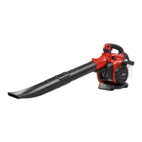
2. Remove the blower tube and install the collection
bag tube. Install and tighten the tube clamp bolt.
Attach the strap to the collection bag loops.
3. Align the arrow on the lower vaccum tube with the
arrow on the upper vaccum tube. Push the lower
vaccum tube into the upper vaccum tube
approximately 7 cm (3 in). Push until the lower tube
is safely attached in the upper tube. Assemble the
two tubes with the supplied screw.
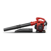
4. Use a screwdriver to open the cover. Put the
screwdriver at the arrow on the inlet cover. The
arrow is below the edge of the cover on the opposite
side of the hinge.
5. Push the vaccum tubes into the large opening at the
bottom of the blower. Align the tabs with the slots in
the tubes. Turn until the bayonet mount locks. The
lock symbols must be aligned.
O
Read and understand the safety
chapter before you operate the product.
This product has a two-cycle
engine. Use a mixture of gasoline and two-
cycle engine oil. Make sure to use the
correct quantity of oil in the mixture.
Incorrect ratio of gasoline and oil can cause
damage to the engine.
Do not use gasoline with an
octane number less than 90 RON (87 AKI).
This can cause damage to the product.
Do not use gasoline with more
than 10% ethanol concentration (E10). This
can cause damage to the product.
• Always use new unleaded gasoline with a minimum
octane number of 90 RON (87 AKI) and with less
than 10% ethanol concentration (E10).
• Use gasoline with a higher octane number if you
frequently use the product at continuously high
engine speed.
• Use only high quality two-cycle engine oil. Use only
an air cooled engine oil.
• Do not use other types of oil.
• Mixture ratio 50:1 (2%)
1 U.S. Gal. 77 ml (2,6 oz)
1 UK Gal. 95 ml (3,2 oz)
5 l 100 ml (3,4 oz)
To make the fuel mixture
Note:
Always use a clean fuel container when you mix
the fuel.
Do not make more than 30 days quantity of fuel
mixture.
1. Add half of the gasoline quantity.
2. Add the full quantity of oil.
3. Shake the fuel mixture to mix the contents.
4. Add the remaining gasoline quantity.
5. Shake the fuel mixture to mix the contents.
6. Fill the fuel tank.
• Always use a fuel container with an antispill valve.
• If there is some fuel on the container, remove the
unwanted fuel and let the container dry.
• Make sure that the area near the fuel tank cap is
clean.
• Shake the fuel container before you add the fuel
mixture to the fuel tank.
To start and stop
Before you start the engine
• Examine the product for missing, damaged, loose or
worn parts.
• Examine the collection bag. Make sure that the
collection bag is not damaged and that the zipper is
closed.
• Examine the nuts, screws and bolts.
• Examine the air filter.
• Examine the throttle trigger for correct operation.
• Examine the stop switch for correct operation.
• Examine the product for fuel leaks.
To start a cold engine
WARNING:
Do not wind the starter rope
around your arm.
238 - 001 - 06.07.2017
 Loading...