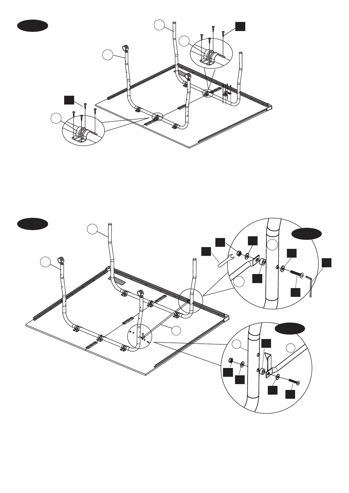
FIG. 5
FIG. 6
H5
H5
H4
H4
H4
H3
H3
H4
H1
H1
H6
H6
Center
Player End
3
2
11
11
2
3
Center
Player End
9
9
3
H9
2
9
FIG.6A
FIG.6B
FIG.5
8. Place the Outer Leg (#2) on the player end of the table half
and the Inner Leg with wheels (#3) on the center end of the
table half.
Inner Leg (#3) using Screws (#H5). There are pre-drilled holes
for the screws.
FIG.5
8. Ponga la pata exterior cerca del lado "Player" y la pata
interior (#3, con las ruedas) cerca del centro de la mesa.
9. Sujete las patas (#2 y #3) a la mesa con los soportes (#11)
usando tornillos (#H5) en los agujeros pretaladrados. Vease
FIG.6
Washers (#H4), one Spacer (#H6) and one Nut (#H3). See
FIG.6A.
FIG.6
10. Sujete el extremo de la barra de vinculacion con la
abrazadera de seguridad (#9) a el lado interior (i.e. el lado
al centro) de la pata exterior (#2) (i.e., la pata sin ruedas)
con un perno (#H1), dos arandelas (#H4), un espaciador
11. Repita este proceso con el otro extremo de la barra (#9),
pero sujetandola al lado exterior de la pata interior (#3).
H8
 Loading...