Do you have a question about the jotron Tron AIS TR-8000 MkII and is the answer not in the manual?
| Channel Spacing | 25 kHz |
|---|---|
| Operating Temperature | -15°C to +55°C |
| Frequency Range | 156.025 MHz to 162.025 MHz |
| Channels | AIS 1, AIS 2 |
| Current Consumption | 1.5 A |
| Transmitter Power | 1 W |
| Standards | IEC 60945 |
| Certifications | MED, FCC |
Guidelines for safe installation and operation of the equipment.
Specifies safe distances from magnetic compasses for the units.
Legal notice regarding the use and reproduction of the manual.
States that information is believed accurate but no responsibility is assumed.
Guidance on proper disposal of electronic waste according to regulations.
Details the IP ratings and protection levels for the units.
Explains the AIS system, its technology, and operating modes.
Details the components included in the standard package.
Refers to the website for available optional accessories.
Refers to the website for available spare parts.
Outlines the main features and capabilities of the AIS system.
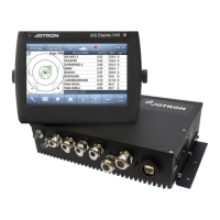
Details the transponder unit, its core functions, and connection possibilities.
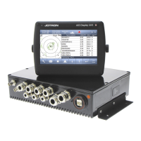
Describes the display unit, its user interface, and key features.
Covers ON/OFF button operations, screen cleaning, and power off procedures.
Describes the main sections (Status Bar, Content, Button Bar) of the display unit menu.
Configuration of voyage-related data like status, destination, and ETA.
Information on using AIS text messages for communication between ships.
Adjusting display brightness and switching between day/night modes.
Guidelines for physically mounting the transponder unit, considering environmental factors.
Guidelines for mounting the display unit in desktop, roof, or flush configurations.
Details antenna placement and separation requirements for optimal performance.
Provides guidance on cable types, installation, and protection for signal integrity.
Illustrates typical wiring diagrams and connection interfaces for system components.
Details the various connection ports and internal wiring of the transponder unit.
Describes the connectors on the rear of the display unit for power and communication.
Provides a step-by-step checklist for initial system setup and verification.
Notes that not all vessels are equipped with AIS.
Discusses the advantages of AIS as an anti-collision aid.
Highlights the risks of incorrect data and the user's responsibility.
Setting static ship data, dimensions, and antenna positions for accurate AIS reporting.
Configuring display appearance, regional parameters, and view modes.
Managing system alarms, their configuration, and understanding operational indicators.
Accessing advanced settings, configuring network interfaces, and ports.
Configuration of network interfaces, IP addresses, and display ports.
Settings for pilot port use, and configuring long-range port for ECDIS or external display.
Setting sensor priorities and using port monitor for connection troubleshooting.
Configuration of VHF link modes and Long-Range communication settings.
Performing communication tests between ships to verify VHF link functionality.
Setting collision alerts and inspecting the internal GNSS receiver functionality.
Reviewing system logs, performing self-tests, and viewing system information.
Procedures for changing administrator and user passwords.
Information on how to update the system firmware.
Information on operating the transponder in European Inland Waterways mode.
Displays decoded fields of transmitted AIS messages.
Mechanical dimensions and drawings for the transponder unit.
Mechanical dimensions for desktop or overhead mounting of the display unit.
Mechanical dimensions and panel cut-out details for flush mounting the display unit.
Technical specifications and dimensions for the SANAV GPS Marine Antenna.
Details on warranty period, claims, and procedures for repair or replacement.
Information on service provisions, installation, and programming by authorized agents.