21
3.0 Installation
3.1 Floor
Foundations
It must be ensured that the foundations are dimensioned for the
fi replace. Cf. «2.0 Technical data» for specifi cation of weight.
It is recommended that fl ooring which is not fastened to the
foundations – so-called fl oating fl ooring – is removed during
installation.
Requirements for protection of wooden
fl ooring
Jøtul F 602 has a heat shield underneath which protects the
fl oor from radiation. The product can therefore be placed
directly on a wooden fl oor that is covered by a metal plate or
other suitable, non-infl ammable material. The recommended
minimum thickness is 0,9 mm.
Jøtul recommends that any fl ooring made of combustible
material, such as linoleum, carpets, etc. should be removed
from under the fl oor plate.
Requirement for protecting combustible
fl ooring in front of fi replace
The front plate must be in accordance with national laws
and regulations.
Contact your local building authorities regarding restrictions and
installation requirements.
3.2 Walls
Distance from the wall of fl ammable
material – cf. fi g. 1
The fi replace is authorised for use with an uninsulated fl ue with
the distances to the wall of fl ammable material as shown in fi g 1.
Distance to the fl ammable wall protected
by a fi rewall
Firewall requirement
The fi rewall must be at least 100 mm thick and be made of
brick, concrete-stone or light concrete. Other materials and
structures with satisfactory documentation may also be used.
3.3 Chimneys and fl ue pipes
• A chimney can be linked to the fi replace and fl ue approved
for solid fuel-fi red fi replaces with a fl ue gas temperature as
specifi ed in «2.0 Technical data».
• The cross-section of the chimney must be at least equal to
the cross-section of the fl ue. Please use «2.0 Technical
data» to calculate the correct cross-section of the chimney.
• Connection to the chimney must be carried out in
accordance with the installation instructions from the
supplier of the chimney.
• Before making a hole in the chimney the fi replace should
be test-mounted in order to correctly mark the position of
the fi replace and the hole in the chimney. See fi g. 1 for
minimum dimensions.
• Ensure that the fl ue pipe is inclined all the way up to the
chimney.
• Use a fl ue pipe bend with a sweeping hatch that allows it
to be swept.
Be aware of the fact that connections must have a certain
fl exibility in order to prevent movement in the installation
leading to cracks. N.B. A correct and sealed connection is
very important for the proper functioning of the product.
The chimney draught, see «2.0 Technical data». If the
draught is too strong you can install and operate a fl ue
damper to control the draught.
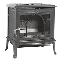
3.4 Assembling the stove
N.B. Check that the fi replace is free of any damage prior to
commencing installation.
The product is heavy! Make sure you have assistance when
erecting and installing the fi replace.
The product is delivered in a single packing case where the
heat shield and door knob must be assembled.
1. Remove the cooking plate and all the separate parts inside
the stove.
2. If it is necessary to protect the walls, use the enclosed heat
shield. Use the bracket to connect the side heat shield (fi g.
2) to the base heat shield. Fasten the bracket in the center
of the base plate with a screw.
3. Guide the fl aps on the top of the side heat shield into the
groove under the top plate.
4. The fl ue outlet (fi g. 3 A) and the blanking plate (fi g. 3 B)
exchange positions if the smoke outlet on top of the stove
is preferred. The two screws on the fl ue outlet may be
somewhat diffi cult to release. Hold on to the nut on the
inside with a small wrench of the fl ue outlet to release the
screws on the outside. Ensure all possible unused fl ue
outlets are suitably blanked off .
5. Place the fl ue pipe’s end outside the product’s smoke outlet.
Fill any gaps between the fl ue pipe and smoke outlet with
suitable gasket.
6. Connect the knob (fi g. 4 C) to the door latch with the screw
and nut provided.
7. Place the stove into its fi nal position and guide the fl ue pipe
onto the stove’s chimney collar and attach it.
8. Follow the installation instructions given by the supplier
of the chimney.
ENGLISH
 Loading...