1
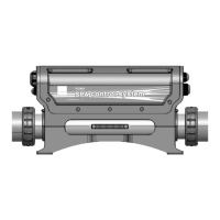
Connect the main power, when the system is powered off
Voltage input:220-240V~ 50Hz/60Hz 1Px32A
I
II
Load configuration
Configure dial switch position A1-A5 according to the dial switch
S1 configuration table (figure on the right) on the control system
PCB
English
S1
ON
OFF
A1
A5
ON
1 2 3 4 5
HEATER_2
J16
TB1
J10
POWERAUX
L N
CN10
250V~/T10A
G N L
G N L
PUMP
CN1
F3
HEATER_1
J15
V+
GB A
V+
GB A
TEMP.
CN20
PANEL
CN25
V+
SIGG
CN24CN23
P25B85
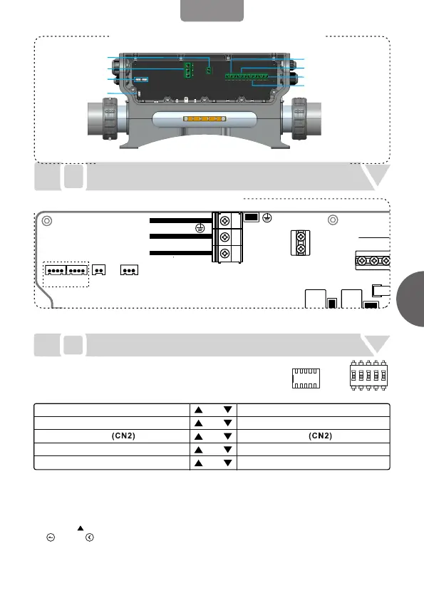
Wiring Diagram
BLUE
BROWN
YLW/GRN
N
L
G
POWER INPUT
LED LIGHT
COM CONNECTORS
WIRING
PUMP1(1 SPD)
BLOWER(OR PUMP2)
OZONE
CIRC PUMP
AUX POWER
Code position A1: If there is only one control system in the whole system, then please
configure A1 as HOST SYSTEM; if there are two control systems in the whole system, then
please configure one control system A1 as HOST SYSTEM, the other control system A1 as
SLAVE SYSTEM.
Configure A2 、A3and A5 according to specific function requirement.
Pull A4 to ON. Power the control system on and enter Set interface in the control panel. Press
“ “ or “ “ for 3 seconds to enter Function interface. Then configure the loads as shown
in the below figure. After configuration, please return to Set interface immediately so that the
configuration can be stored. Note: the configuration must be done within 60 seconds after the
control system is powered on.
1.
2.
3.
HOST SYSTEM SLAVE SYSTEM
BLOWER OUTPUT
PUMP2 OUTPUT
A5
A4
A3
A2
A1
POWER LIMIT
PUMP1 1 SPEED
POWER NOT LIMIT
STORE SETTING
SETTING
PUMP1 2 SPEED