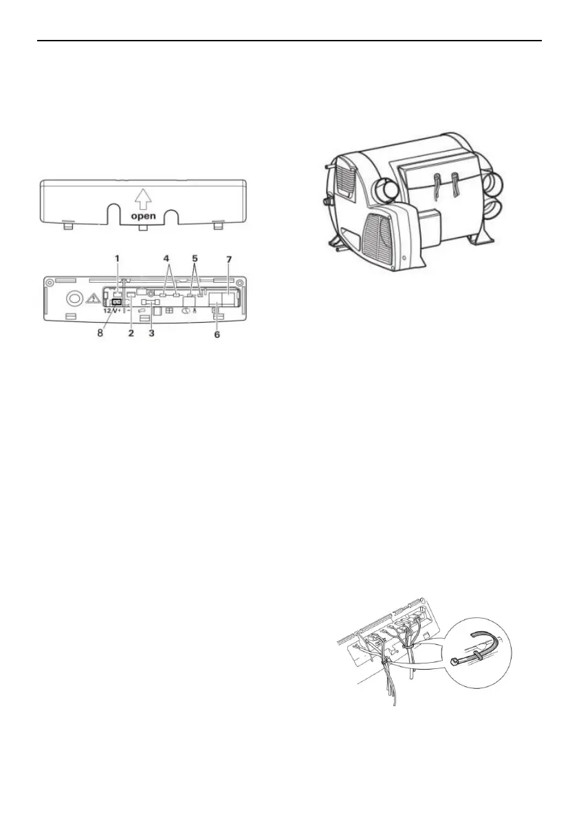
1-DC12V positive 2-DC12V negative
3-Fuse 4-Window Switch
5-External Temperature sensor
6,7- Control switch 8. fuel pump
When the window switch is not installed, the short
connecting wire cannot be removed.
All cables connected to the heater must be hung in the
direction of sagging. This will prevent condensate water
slipping off from the connector cable and into the heater.
The connector cable and plug must be free of force.
Bundling connector cable (See Figure 23), attach it to
the housing with a cable tie to eliminate tension.
All cables must be securely connected and must not be
loose or disconnected due to vibrations, causing a fire
hazard!
 Loading...