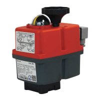
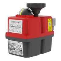
Quick Start Guide J4C S20-S300
Actuated Valves Supplies Ltd
These J+J quarter-turn electromechanical actuators are designed to control and regulate industrial valves.
To maximize versatility, the actuator has a large number of optional modules to argument its operation and an easily configurable
cam system. In the standard version, the drives are pre-adjusted to 0°-90° (0° = closed / 90° = open). Other rotational angles are
also configurable.
The following Quick Start Guide will guide you through all the necessary steps for installation and operation of the actuator.
Please read these carefully before installation.
For special versions, please also refer to the enclosed instructions and the plate.
Function
The actuator automatically detects the operating voltage. Depending on the control signal, it then moves in either a clockwise or
anti-clockwise direction to the predefined end position, which can be set with the cam system and monitored by the limit switches.
The status signals are enabled before the actuator reaches the desired end position using the cam system and two other volt-free
limit switches. During operation, the brushless motor drives the main shaft through the gearbox, the dome position indicator will
reflect the current position of the valve. Additionally, the operational status is displayed with a multicolored status LED located on
the top of the device.
To prevent condensation buildup in the housing, usually as a result of fluctuations in the external
temperature, the actuator has an automatic, integrated, heater which protects the circuitry (permanent power supply required).
If the valve becomes blocked or jammed, the automatic electronic torque limiter will stop the motor to protect against damage to
the gearbox and motor.
In the event of a power failure or emergency-stop, the manual override can be switched on via the changeover switch and the
driveshaft can then be manually actuated via the handwheel.
Connection
The mechanical connection is made via a standardized mounting according to DIN 3337 / ISO 5211. Each
actuator has a multi-flange plate and is compatible with various shaft mountings. The electrical connection is
made via industrial standard connectors.
Options
Optional moduals are available for a wide variety of functions (refer to product data sheets):
• BSR Battery Failsafe / DPS Digital Positioning System / Potentiometer / different wiring options.
• Golden Contacted Limit Switches for volt-free end position feedback (z.B. SPS) 0,1A 30VDC
Maintenance
Maintenance work is not necessary on J+J rotary electric actuators, however a regular check of the unit’s function is
recommended, especially for rarely used or emergency use actuators.
Important Instructions
All operating instructions must be read carefully and completely before installation.
Where additional models are used, the instructions supplied with the modules should also be read.
Parts of these devices operate under dangerously high voltage. Failure to observe general electrical
safety rules and policies may result in serious personal injury or property damage. Only suitably
qualified personnel should work on or near these devices. All personnel must be familiar with all safety
instructions and maintenance measures in accordance with these operating instructions.
Fault-free and safe operation of these devices require proper transportation, storage, installation /
assembly, as well as careful operation and routine checks.
Notes on the configuration
Before using the actuator, ensure all connections, fittings and surrounding areas are safe, otherwise, long-term damage or
functional failures may occur.
Environment and installation
J+J actuators must not be installed inverted (flange facing upwards). It is important to pay attention to the accessibility of manual override
and visibility of position indicator as well as the status LED when planning your installation.
For applications with vibrations in the pipeline, compensators must be provided.
If the actuator is to be used outdoors, adequate protection (roofing) against adverse weather must be provided.
Strong sunlight can damage the housing due to heat and UV radiation. If the drive is used in
freezing conditions, ice can lead to the manual override becoming unusable.
To avoid condensation, the heater must always be active (permanent electrical connection).
-PAGE 1-