84
Index
ASSEMBLY INSTRUCTIONS - BSR KIT 20/85
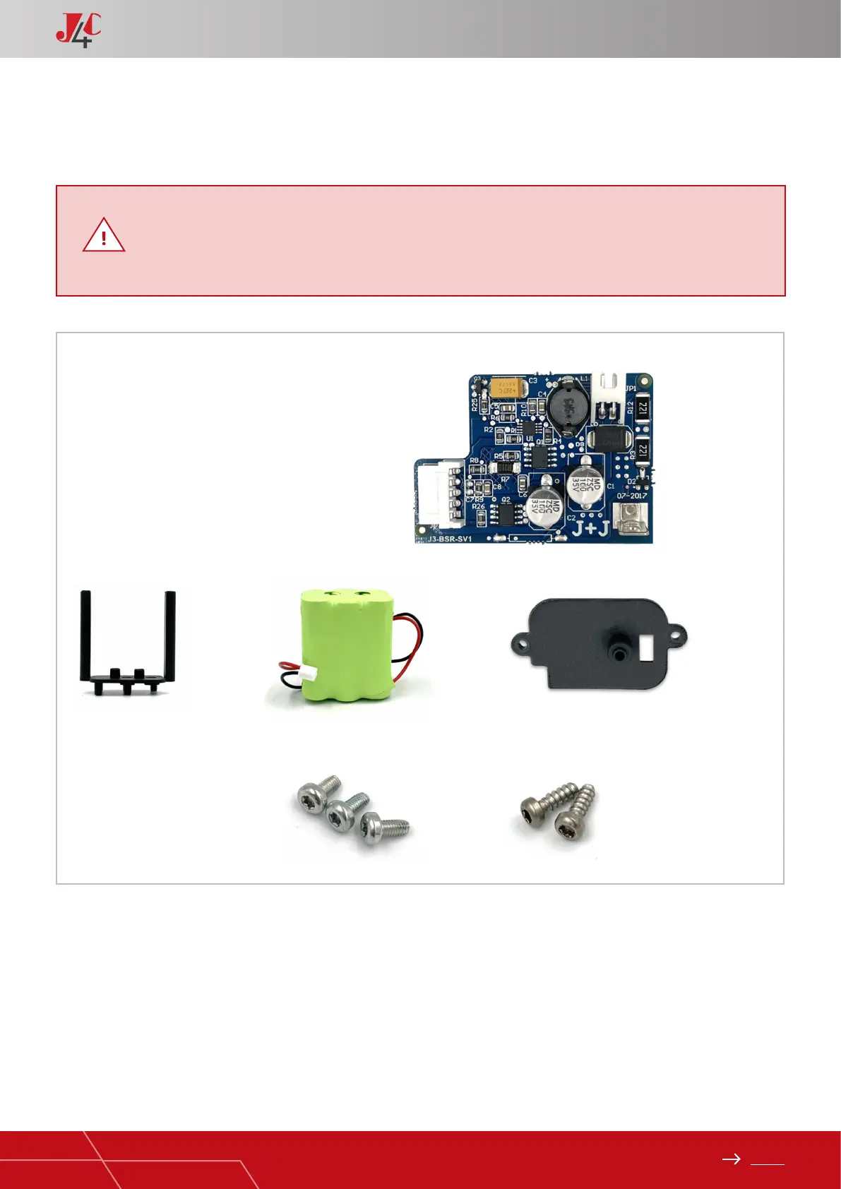
KIT COMPONENTS
Element A - 1 BSR PCB.
Element B - 1 Lower battery support.
Element C - 1 Battery pack.
Element D - 1 Upper battery support.
Element E - 3 Sheet metal Fixing screws.
Element F - 2 Plastic Fixing screws.
* Fill in the document inside the kit, and send it to e-mail: info@jjbcn.com or the fax number (93 871 32 72), shown in
the document.
A
B C D
E F
Very important!
Please, follow these instructions step by step. If the connector of the battery pack is plugged into
the “BSR” pcb, before arriving to point 7, the pcb could be damaged.
HANDBOOK / KIT BSR
 Loading...