Quick Start Guide J4C S20-S300
Actuated Valves Supplies Ltd
Cam Adjustment
By adjusting the cams, the swivel angle as well as the end position feedback of the drive can be configured.
The drive is pre-adjusted ex works (see type plate). Depending on the application, or lack of alignment when fitting, it may be necessary
to adjust the actuator's travel.
All work on the open drive must only be carried out under the safety of extra-low voltage or in the de-energized state and
by a suitably qualified specialist.
Failure to follow the general electrical safety procedures may result in serious personal injury or property damage.
1. Opening the case
Required tools: Allen key 3mm (Model 35-300), Torx wrench (T20)
To adjust the cam system, the housing must first be opened. Particular care should be taken to ensure that all gaskets and
screws are carefully stored. The following steps have to be carried out:
• Unscrew and remove all plugs (pay attention to seals)
• Release screw in the handwheel and pull handwheel upwards
• Loosen and remove the housing screws
• Disconnect the housing cover and lay the cover aside (cables can remain connected to the board) and make a note of the
original cable routing.
• Put handwheel back on
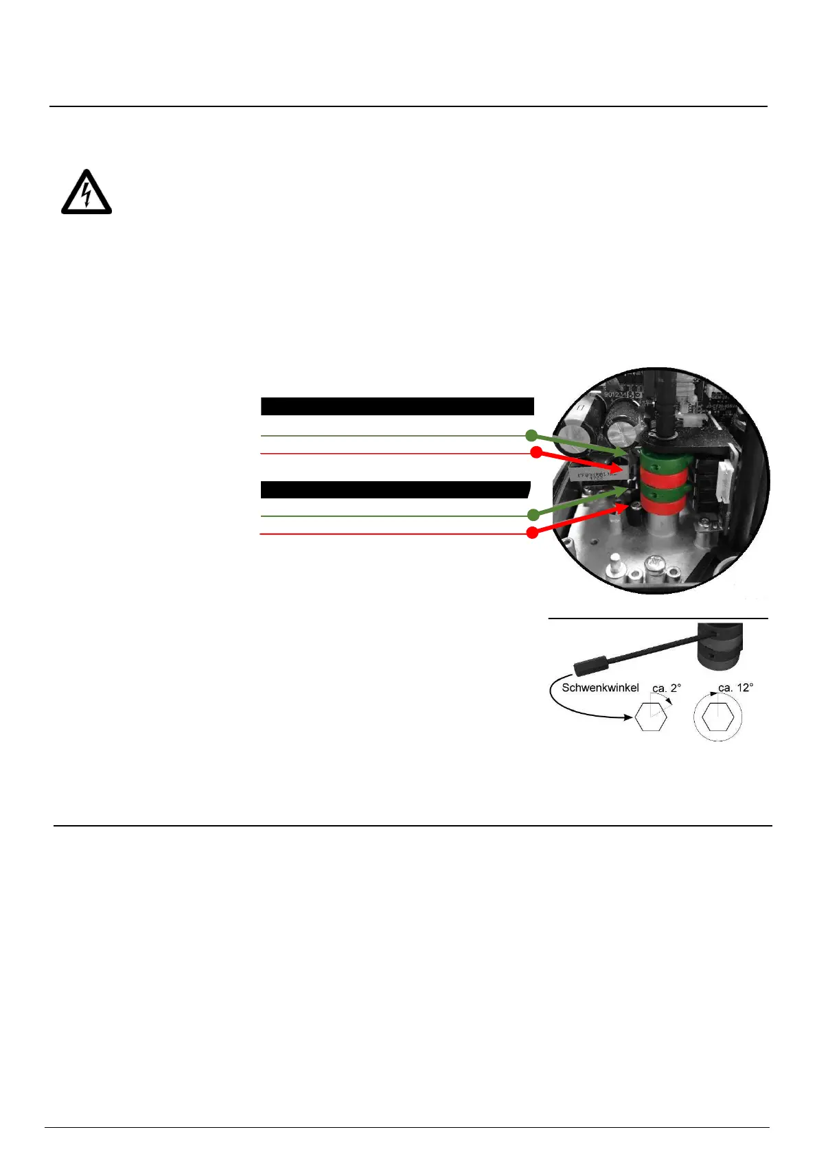
2. Adjust the cams
To adjust, the adjustment tool,
which is attached to the engine
bust be removed.
Insert the tool into the respective
cam as shown.
By turning the tool, the cam can
now be adjusted.
Volt-free end position feedback
Cam 1
(Green)
Position “open”
Cam 2
(Red) Position “closed”
Cam 3
(Green)
Position “open”
Cam 4
(Red) Position “closed”
Action: The drive must initially be switched from AUTO to MAN.
The cam is moved with the adjusting tool until the click sound of the microswitch is heard. The
cam must always be turned from the direction of the switch, from which the main shaft will
move to this position during operation.
The end position feedback is set so that it switches shortly before reaching the end position
.
The correct setting of the cam positions must always be checked by means of an
electrical test drive (using extra-low voltage for safety). The end positions can then be
measured with a continuity tester on the plug (see wiring diagram)
.
3. closing the case
After completion of the adjustment, the drive can be closed again by reversing the steps described under point 1. Particular
care must be taken to ensure that all screws, seals, individual parts and the internal cabling are returned to their original
positions.
Troubleshooting
The drive moves and then stops. The LED flashes red or green.
»» Operation suspended due to obstruction in operation. Valve and pipeline must be checked!
»» Too weak model selected.
Drive is in position "open" but the valve is closed or half open.
»» Drive has become twisted in relation to the valve. Disassemble drive, move to correct position with handwheel, remount.
The limit switches for end position feedback do not work.
»» Check the wiring. Check the adjustment of the cams so that they trigger shortly before reaching the end position.
The drive moves, the valve does not move.
»» The adaptor between actuator and valve is damaged or incorrectly dimensioned.
For other malfunctions, please contact our technical service department (info@actuatedvalvesupplies.com).
-PAGE 4-
 Loading...