79
Index
HANDBOOK / KIT DPS
ASSEMBLY INSTRUCTIONS - DPS KIT 140/300
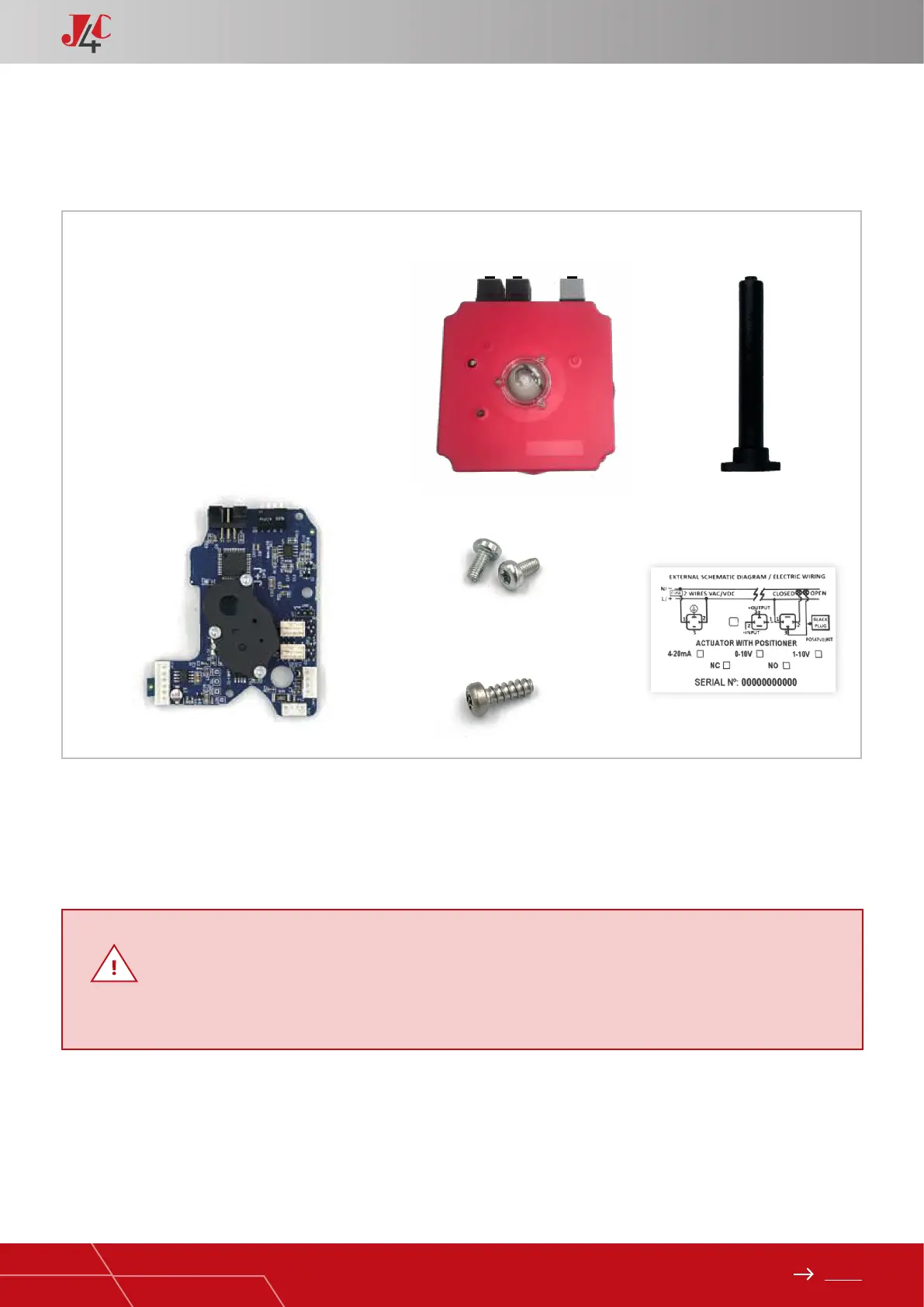
KIT COMPONENTS
Element A - 1 Cover
Element B - 1 Plastic column
Element C - 1 DPS positioner PCB
Element D - 2 Sheet metal Fixing screws
Element E - 1 Plastic Fixing screws
Element F - 1 Schematic diagram label
* Fill in the document inside the kit, and send it to the fax number (93 871 32 72) or e-mail: info@jjbcn.com, shown in
the document.
* Remember to stick the (F) label on the actuator.
Very important!
Please follow the instructions step by step. Before connecting “A” plug to the actuator, check that
the voltage is the same as the one specied on the label (carter). To convert a standard (on-off)
J4C electric actuator into a modulating function with positioner, proceed as follows:
A B
C
D
E
F