- 5 -
3.3 Installation Procedure
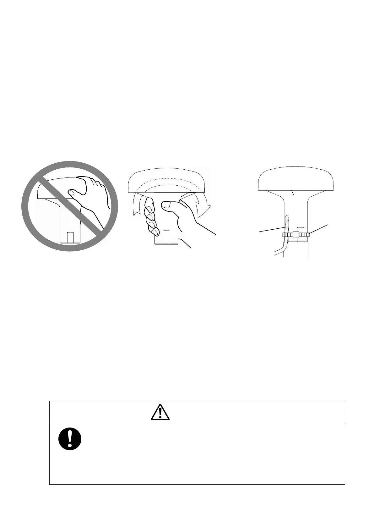
The base of the GPS124 is designed so that it can be installed on the navigation antenna mount unit
or on an extension mast that conforms to 1” x 14 NPT standards. The bottom of the receiver is
provided with a slot to allow the receiver cable to be pulled out to the side. This eliminates the need
of pulling the cable through the center of an extension mast. If the cable is fed through the center
of a mast, the cable connector will have to be removed.
Caution:
When turning the receiver, be careful not to damage the cable and the plastic top cover of the
receiver. (See Figure. 3-1.)
When the cable is fed internally through the extension mast, it is recommended that RTV silicon
sealant be used to seal off the cable slot on the bottom of the receiver as a protection from the
environment. If the cable is laid sideway through the slot, secure it in position to reduce the
damage by vibration. Then seal the slot on the receiver bottom with the RTV silicon sealant.
(See figure.3-2)
3.4 Cable connection
3.4.1 Connection to Navigation Equipment that can be connected directly
CAUTION
When you connect the GPS124 to the navigation equipment that is possible
to connect directly, confirm the type of connector and pin arrangement
beforehand. If the possibility of direct connection with GPS124 is not
described in the manual of the navigation equipment, confirm the all pin
assignment. Incorrect pin connection may cause a damage of the equipment.
Cable tie or
Tape Cable
Seal with
RTV
Do not turn and grip the
cover
Grip the base to turn
Fig.3-1 Installation
Fig. 3-2 Appearance
 Loading...