SHIFS
MAIN
ACIqr/l10v
aaaaaaaaaaaoaaaaaaaoaaaataooaaaooa
aooaa
NNKE-10&9-7 SCAI.INERUNIT
14 CORES COMPOSIET
CABLE
CIRCUN AREAIGR
H-28951 1 {Xt50
MAX 3OMT
d
23
(JRC
SUPPL\')
NTG-3028 TMNSMFTER-RECETVER
UNIT
14 CORES COMPOSIET CABLE
H-20951 10050
rrAx 3sMT
d23
(JRC
SUPPLY)
NC}./t263 DISPLAY
UNIT
SHIP'S MAIN
AAlOO/1rO/22O1/23tN
50/6OHz, I
tb
AC220/2
V
s6
GYRO
LOG/DLOG
GPS
Ats
ECHO SOUNOER
ALARM
MONITORNG
6(X)VA
ECIDS
CONNNG
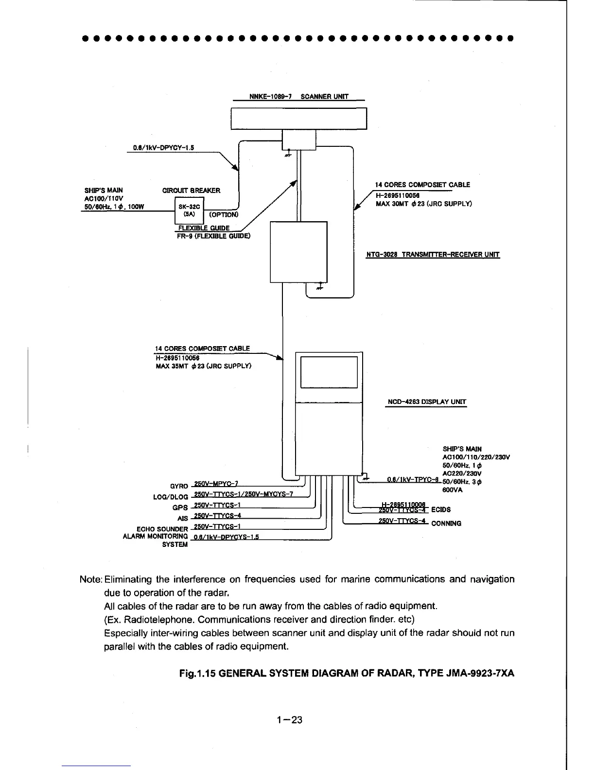
Note:
Eliminating
the interference
on
frequencies
used
for marine communications and
navigation
due
to ooeration of the
radar,
All
cables of the radar are to be
run away from the cables of
radio equipment.
(Ex.
Radiotelephone. Communications
receiver
and direction
finder. etc)
Especially
inter-wiring cables between
scanner
unil and display
unit of
the radar
should not run
parallel
with the
cables of
radio equipment.
Fig.1.15 GENERAL
SYSTEM DIAGRAM OF
RADAR, TYPE JMA-9923-txA
SYSTEIT
1-23
 Loading...


