Do you have a question about the JRC JST-100 and is the answer not in the manual?
Check included accessories against the packing list.
Select a suitable location considering ventilation and environment.
Details on connecting power, antenna, earth, and peripheral units.
Connect the DC power source, checking voltage and current capacity.
Connect antenna, ensuring 50-ohm impedance and proper matching.
Importance of good ground connection for safety and interference reduction.
Connect microphone to MIC connector, specifying impedance/sensitivity.
Connect CW key to the rear KEY connector, specifying voltage limits.
Connect external speaker or use internal speaker, specifying impedance.
Connect electronic keyer, noting TTL level requirements for keying.
Connect antenna tuner for impedance matching when SWR is high.
Connect linear amplifier, including antenna, earth, standby, and ALC lines.
Connect RTTY equipment for AF output, keying, and standby signals.
Details on connector for various input/output signals and peripheral units.
External control of frequency and mode via memory connector.
Connect external antenna tuner using internal frequency data.
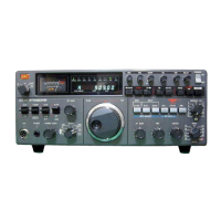
Details of all controls on the upper and lower front panels.
Detailed description of each front panel control and its function.
Description of rear panel connectors, terminals, and jacks.
Overview of all rear panel connections and their purposes.
Procedures and settings for receiving various signals.
Step-by-step guide for setting up and performing reception.
How to interpret the frequency display and VFO indicator.
Procedure for receiving Single Sideband signals.
Procedure for receiving Continuous Wave signals.
Procedure for receiving Radio Teletype signals.
Procedure for receiving standard radio waves (AM).
Features for selecting desired signals and reducing interference.
Function and adjustment of the receiver attenuator.
Selection of AGC time constants for different signal conditions.
Adjusting RF and IF amplifier gain for optimal reception.
Narrowing IF pass-band to reject adjacent interference.
Eliminating interfering signals that cause beating.
Reducing impulse noise and sharp burst signals.
Using VFOs for receiver incremental tuning.
Procedures for transmitting signals in different modes.
General steps for preparing and performing transmission.
Procedure for transmitting SSB signals.
Procedure for transmitting CW signals.
Procedure for transmitting RTTY signals.
Functions related to transmitting output.
Using voice activation for transmit/receive switching.
Increasing mean talk power for SSB transmissions.
Utilizing two independent VFOs for advanced operations.
Basic operation using two VFOs for simultaneous transmit/receive.
Operating with different transmit/receive frequencies.
Advanced split operation for specific calling scenarios.
Utilizing the 11-channel memory for storing frequencies and modes.
Steps for storing frequency, band, and mode into memory.
Methods to recall stored frequency data into VFOs.
Using the memory finder feature to locate stored data.
Important precautions when using the memory functions.
Adjusting optional features for optimal performance.
Setting anti-trip to prevent accidental transmit during VOX.
Adjusting side tone frequency and level for CW monitoring.
Setting the AF signal level for the LINE OUT connector.
Setting the ALC operation starting level for linear amplifiers.
Limiting output power to 50 watts using the REDUCT switch.
Connecting an external receiver to the RX ANT jack.
Procedure for safely removing upper and lower covers for maintenance.
Diagram showing the location of internal units and boards.
Instructions on how to remove internal PC boards using pullers.
Procedures for adjusting the 10MHz reference frequency.
Adjusting 10MHz frequency using a counter and trimmer capacitor.
Adjusting 10MHz frequency using standard radio waves.
Guidance for resolving operational issues and symptoms.
Common receive problems and their solutions.
Common transmit problems and their solutions.
Resolving issues related to frequency selection and control.
Details of the voltage-regulated power supply for fixed stations.
Description of the antenna tuner for impedance matching and SWR measurement.
Specifications for the separate type speaker matching the main unit.
Specifications for the desk microphone, including sensitivity and impedance.
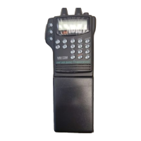
Specifications for the hand microphone, including sensitivity and impedance.
Specifications for the CW key, including dimensions and weight.
CW filter for sharp selectivity and rejection of radio interference.
Crystal filter for higher selectivity in CW reception.
Instructions for mounting optional filters onto the IF AMP unit.
Technical details including frequency ranges, modes, and power.
Specifications for the transmitter, including output power and suppression.
Specifications for the receiver, including sensitivity and selectivity.
Overall block diagram of the JST-100 HF transceiver.
Circuit diagram for the Band Pass Filter unit.
Circuit diagram for the RF Amplifier unit.
Circuit diagram for the Intermediate Frequency Amplifier unit.
| Mode | FM |
|---|---|
| Sensitivity | 0.25 μV for 12 dB SINAD |
| Image Rejection | 70 dB |
| IF Rejection | 70 dB |
| Voltage | 13.6 V DC |
| Power Supply | 13.8 VDC |