Do you have a question about the JRC JST-135 and is the answer not in the manual?
Details the signal path through the transceiver.
Explains the frequency synthesis circuitry.
Overview of the transceiver's six blocks and optional units.
Description of the RF tuning circuitry.
Detailed explanation of the IF filter unit.
Description of the IF amplifier unit.
Description of the Power Amplifier unit.
Details the Low Pass Filter unit circuitry.
Description of the Reference DDS unit.
Description of the Notch Follow Unit.
Description of the ECSS Unit.
Description of the RS-232C interface unit.
Settings and controls for preparing adjustments.
Specific settings for controls before adjustment.
List of instruments needed for calibration.
Diagrams for sensitivity and power output tests.
General overview of unit-specific adjustments.
Procedure for adjusting the PA unit.
Procedure for calibrating the AF AMP unit.
Procedure for adjusting the CPU unit.
Procedure for adjusting the display unit.
Procedures for Loop1 unit adjustments.
Procedures for REF DDS unit adjustments.
Procedures for IF AMP unit adjustments.
Procedures for IF Filter unit adjustments.
Adjustments for the receiver circuitry.
Adjustments for the transmitter circuitry.
Circuit diagram for the RF Tune Unit.
Component layout for the RF Tune Unit.
Circuit diagram for the IF Filter Unit.
Component layout for the IF Filter Unit.
Circuit diagram for the IF AMP Unit.
Component layout for the IF AMP Unit.
Circuit diagram for the CPU Unit.
Component layout for the CPU Unit.
| Brand | JRC |
|---|---|
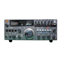
| Model | JST-135 |
| Category | Transceiver |
| Language | English |