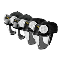
UNPACKING AND INSPECTION: The following items should all be within the carton:
STORAGE: When not in use or during transportation, Powercap
®
Active
™
should be stored in the packaging in which it was supplied. Powercap
®
Active
™
should be stored away
from direct sunlight, not in contact with solvents and in such a manner that it cannot be damaged by physical contact with hard surfaces. Storage temperature should be between
5°C and 40°C and relative humidity not greater than 75%. During storage, the power cable should be disconnected from the PowerBox™1 battery pack.
Fitting the visor - PowerCap
®
Active™:
1. Remove the old visor by peeling it away from the Velcro
®
sections on the inside of the brim.
2. Align the Velcro
®
sections on the visor with the Velcro
®
sections on the inside of the brim, ensuring that the visor is central. Press the Velcro
®
sections together making certain
that the visor is rm against the underside of the brim.
BATTERY AND AIRFLOW CHECK: Powercap
®
Active
™
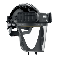
has a Minimum Design Flow rate of 140 l/min. To check
battery charge and airow the lters must be tted and the visor removed (See Image 3). Removal of visor for
airow check is only relevant to Non-Impact Powercap
®
.
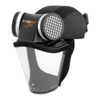
Having removed the visor insert the male connector at the end of the Powercap
®
Active
™
“Power cable” into the
female connector on the PowerBox
™
1 battery compartment (See Image 4).
To check the battery charge, press the power button once. To switch the unit on and off, press and hold the
power button rmly for 2 seconds (See Image 5). Airow will now commence. It is now necessary to check that
the airow is sufcient, and the following checks should be carried out on a regular basis with the lters tted and
always before use of Powercap
®
Active
™
:-
USING THE PowerCap
®
Active
™
Unit: The Powercap
®
Active
™
meets the TH1P requirements of EN 12941 this offers protection against ne non-toxic bres, fumes and dusts.
Operating temperature should be between 5°C and 40°C and relative humidity not greater than 75%.
FILTERS: The lters provided are high efciency sub-micron particulate types supplied in pairs. They will lter most particulate matter such as dust, spores, mist and fumes, but like
all lters cannot lter out all particulate matter present in the air. They will not lter gases, vapours or toxic substances.
• The duration of lter life will depend mainly on the amount and size of the contamination in the area where they are used, and the time used in that area. Inspect the lters regularly.
Ensure that they are located correctly and carefully remove any visible large surface contamination to prolong their life. The lters must not be washed or allowed to get wet. A low
airow reading (red section of indicator) usually indicates that new lters are required.
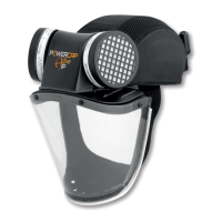
FITTING AND REPLACING THE FILTERS: Only replace with a pair of genuine replacement lters (at the same time) from JSP Ltd or its distributors.
Simply twist anticlockwise, with lter towards you, and lift away from motor housing (Image 1). Replacement is the reverse procedure. Ensure that the lter and motor housing mating faces
are clean; do not allow any dust or foreign objects to fall into the motor housing. Push and twist the replacements rmly into place (Image 2). Recheck airow when the new lters have
been tted before use. If the lters are not tted correctly, ltering efciency will be severely reduced.
Removal Replacement
1 2
REPLACING THE PRE FILTER PAD: The Powercap
®
Active
™
lter includes a pre lter cover that is situated underneath the grill lid of the lter. There is a removable lid just above
the label of the lter, remove this lid, replace the pre lter pad and replace the cover ensuring that it is back in place correctly. Regular replacement of the pre-lter pad will help the air
ow of the product. The pre lter pad helps to protect from the larger airborne hazards (>10µm) whilst the actual lter protects from the smaller airborne hazards.
Note: PowerCap
®
Active™ also provides protection to EN 812, the BumpCap standard.
It should be noted that the special liner for this protection forms an integral part of the cap structure. Ensure that the bump cap liner is tted into the Cap before use.
Invert (turn upside down) the Powercap
®
Active
™
and t the Airow Indicator supplied over the air outlet inside
the rim of the Visor Carrier ensuring a good seal. Avoid placing hands or other possible obstructions over the
two lter inlets (See Image 6).
Check that the white ‘ap’ at the bottom of the Airow Indicator moves freely. The “ap” indicator within the airow device should
move into the “green section” which means that there is adequate airow for PowerCap
®
Active
™
to be used.
In the event of no ow or low ow indicated by a move of the ap into the “red section”, rst recheck the battery
tting or charging condition. In the event that there is still no or low airow, do not use the PowerCap
®
Active
™
,
but contact JSP Ltd for further advice.
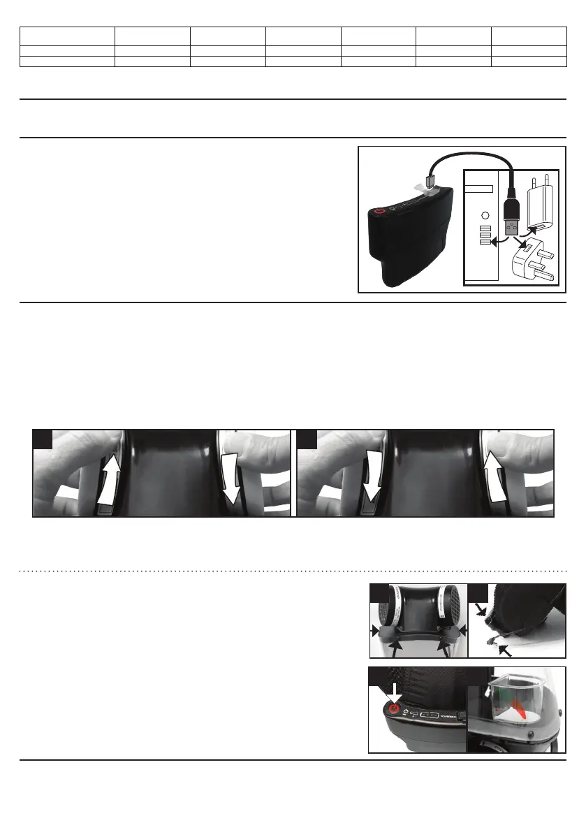
LITHIUM ION POWERBOX™1 BATTERY PACK: When turned on, the Lithium Ion battery has green, amber
and red lights on the outside to show the level of charge; green being fully charged.
Charging the batteries: Switch off Powercap
®
Active
™
, remove the dust cover, and connect it to a USB
charge point using the Micro USB cable provided. A 5-8 hour charge will produce 8 hours of run time from
Powercap
®
Active
™
.
Precautions on charging:
• Avoid charging in direct sunlight or in a vehicle parked under direct sunlight, and make sure to charge only
when the ambient temperature is between +5°C and +40°C.
• Before charging, ensure that no dust or other foreign objects attach to the USB plug.
• Do not subject the device to vibrations while charging.
• When your PC is in sleep state, the unit cannot be charged.
• Once charging is complete, ensure that the USB plug is disconnected.
• If the function time is signicantly reduced even after proper charging, the rechargeable battery may be
nearing the end of its service life.
• Dispose of batteries in accordance with local regulations.
ITEM
Cap c/w rigid
Impact-Liner
PowerCap
®
Active™
Drive Unit
1mm
Polycarbonate Visor
0.35mm
Polycarbonate Visor
PowerBox™1
Battery Pack
Airow Test Unit
PowerCap
®
Active
™
PowerCap
®
Active
™
IP
3 4
5 6
3
 Loading...