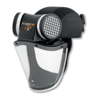
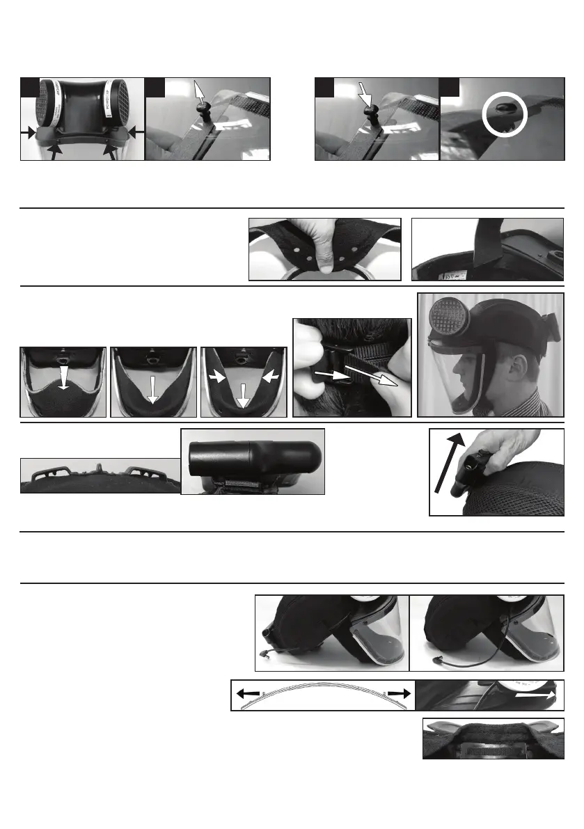
REMOVING/FITTING THE VISOR - PowerCap® Active™:
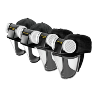
• Remove the skirt from the visor, and then remove the visor by rst pulling out the central pin of all four push-rivets around the carrier and then removing the outer sleeves (See Images 1 and 2).
• Peel back the protective lm from along the top edge of both sides of the new visor. (NOTE: To prevent ngerprints on the visor, leave the rest of the lm in place).
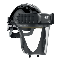
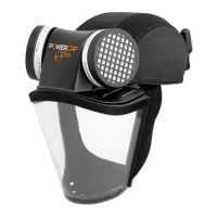
• Using the new rivets supplied, attach the left hand side of the visor to the left hand side of the visor carrier. Ensuring the rivet has passed through both sides of the carrier (See Images 3 and 4).
• Repeat the above procedure for all the four rivets around the visor carrier, some manipulation of the visor may be necessary to achieve a tight seal around the upper edge of the visor.
• Finally remove the rest of the protective lm and re-attach the foam skirt to the Velcro
®
strips.
FITTING FACESEAL SKIRT: The skirt is attached to the side of the
visor and tucks inside the edge of the cap. The edge of the skirt should
be pressed against the Velcro
®
strip down the edge of the visor. The
skirt should look as shown in the pictures when correctly tted.
PowerBox
™
1 can easily be
removed for charging or
replaced with a fully charged
unit to allow for extended shift
patterns. Slide the PowerBox
™
1
unit upwards, disengaging from
the moulded loops. Remove the
Power Cable before removing
the battery from the cap.
FITTING: With sufcient airow checked as described and the Power Cable connected
to the battery, place Powercap
®
Active
™
on the head. It is important that the edge seals
on the side of the visor t closely to the side of the face. The wearers chin should rest
on the lower circular section of the Seal Skirt, bringing the sides of the seal skirt to fold
in on itself.
Adjust the sizing band at the rear of the
cap for a snug and rm t on the head.
GENERAL USE: The battery pack for the
PowerCap
®
Active
™
is designed to be mounted onto
the moulded loops stitched onto the rear of the Cap.
When not in use the battery should be switched off and/or the plug disconnected to conserve the batteries.
Avoid storage of the battery compartment in low temperature conditions, 5°C or lower, as this will have a
detrimental effect on the power capacity of the batteries and could lead to “low ow” performance.
PARTS REPLACEMENT, CLEANING AND DAILY USE: Under normal conditions and assuming regular maintenance, the PowerCap
®
Active™ motor unit should last for 2 - 3 year.
Replacements for all parts are available (contact JSP Ltd for advice); some parts may require the unit to be returned.
Always check the airow level before use, using the airow indicator provided. Prior to use of the PowerCap
®
Active™, the user must check all components and satisfy themselves
that it is suitable for use, if any parts need replacing follow instructions below.
Changing / Washing the Cap: The
Cap can easily be removed from
the Drive-Unit whilst preserving all
other parts. Unplug the PowerBox
™
1
from the Power cable. Remove
PowerBox
™
1 from its moulded loops.
Feed the Power cable through the
channel at the side of the Cap.
Carefully spread both up-stands on the upper surface of the Visor-
Carrier apart until they release the Drive Unit & Visor assembly.
When the PowerBox
™
1, Drive Unit & Visor assembly has been removed, remove the Cap’s Impact Liner by unfolding the towelling
sweatband. The Cap can be machine washed at 40°C. If the Cap requires replacing, do so using only a genuine replacement
supplied from JSP Ltd or its distributors. During re-assembly, ensure that the impact Liner will rest between the rear of the rigid
peak and the wearers head and will be covered by the towelling sweatband.
To replace the Drive Unit & Visor assembly; reverse the above process, ensuring that neither the Power cable nor the Seal Skirt is trapped between the Drive Unit and Cap Peak -
The Power cable stays above the peak. The Seal Skirt ends go below the peak. Ensure that the Drive Unit & Visor assembly has rmly located into the recess in the Cap peak and
that the locking hooks on the Cap Peak have securely fastened onto the Drive-Unit hooks.
Cleaning the Cap and Housing:
The Motor/Filter housing should be
cleaned only with a lightly damped
cloth and mildest detergent. Care
must be exercised to avoid any
liquids entering the motor/fan
assembly or damaging/wetting the
inside of the lters.
1 2 3
4
CLEANING THE VISOR:
• Use only a damp cloth with mild detergent and water. DO NOT USE abrasive cleaners.
• DO NOT rub the visor, use a sweeping motion in one direction lightly pressing the visor.
• Pat the visor dry using a lint free cloth.
4
 Loading...