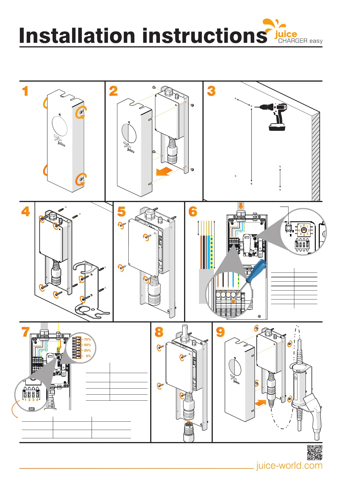
IMPORTANT: May only be installed by an electrically skilled person
Clampable cross-sections
Fine-wire conductor 0.5 - 10 mm² / 20 - 8
AWGFine-wire conductor, wire-end ferrule with plastic collar 2.5 - 6 mm² / 16 - 10 AWG
Ø 6 x 35
100 mm
400 mm
120 mm
Ø 6 x 50
1
2
4
3
5
6
1
5
6
0
7
2
3
4
150 mm
Charging always
activated
Charging with RFID
activation
8
1
2
3
4
9
13 - 15 mm
RJ45 communication
interface*
Delete button
Cable connection
Connector cable Type min. 3 x 2.5 mm² - L1/N/PE
Connector cable Type max. 5 x 10 mm² - L1/L2/L3/N/PE
Connector cable Ø dia. 16 - 21mm
*The power provider may demand that it be possible to reduce the
charging station power or the station entirely disconnected via a digital
signal. This signal can be received via RJ45 communication interface or
dry-contact inputs.
The most recent version of this guide and further information can
be found online at juice-world.com/installieren/juice-charger-easy
Art. EA-JCE1 V2.05 14.04.2021
Example
calculation for 32 A
Charging current 20 A
(rounded from 24 A)
0%
25%
50%
75%
These inputs are dry-contact
inputs, meaning that they are
activated when electrically
connected without voltage. The
result of the calculation below is
always rounded downward to the
next lower charging power.
7
Load shedding connection
via dry contacts:
 Loading...