– 53 –
o If the clearance is larger than the
specified value, detection failure
may result.
o If the clearance is smaller than
the specified value, the knee-
lifter detection seat (asm.) may
interfere with the knee-lifter
sensor , resulting in breakage
of the sensor.
o If the amount of play is 0 mm or
holding the components with an
excessive pressure, the knee-
patch plate (asm.) may
maloperate.
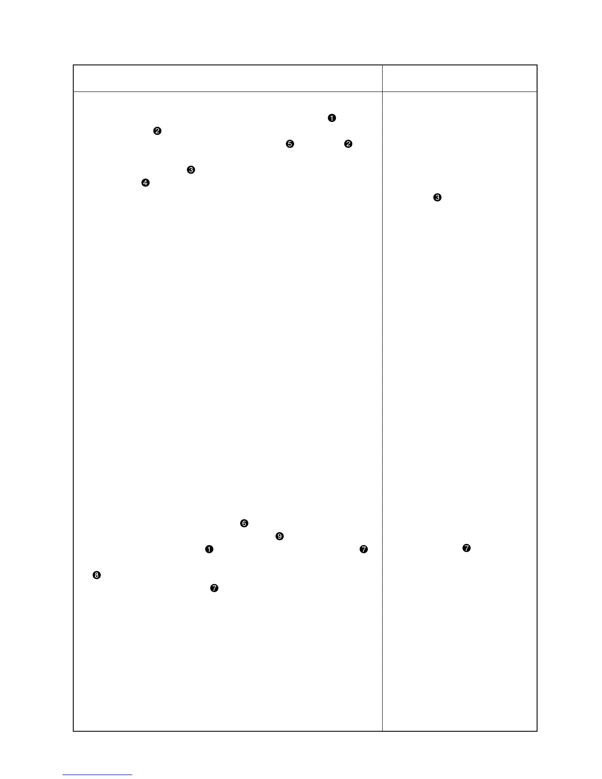
1) Assembling the knee-lifter detection sensor plate (asm.)
1. Remove the knee-lifter plate vertical shaft installing arm and the
two setscrews that are temporarily fixed on the bottom cover.
2. Attach knee-lifter detection sensor plate (asm.) with screw at a
position where a 0.5 to 1.0 mm clearance is provided between knee-
lifter detection sensor and the periphery of knee-lifter detection
seat (asm.) .
2) Assembling the knee-patch plate (asm.)
1. Apply the knee-lifter working shaft to the boss end plane of the
bottom cover, and fasten it with the setscrew by pinching the knee
vertical shaft mounting arm provided with the knee-patch plate .
Adjust the play of the axial direction of the knee-patch horizontal shaft
to approximately 0.2mm.
2. Check that knee-patch plate smoothly move.
Adjustment Procedure
Results of Improper Adjustment
 Loading...