Do you have a question about the JUKI LS-341N and is the answer not in the manual?
Read safety instructions carefully and understand them before using your LS-341N.
Observe basic safety, read instructions, use conforming machines, keep devices in position, use trained operators.
Maintenance by trained personnel; electrical repairs by qualified technicians; stop machine on failure.
Power off for maintenance, handle oil carefully, avoid tampering with live parts, manage pneumatic systems.
Operate in clean environment, ground machine, use for intended purpose, avoid unauthorized modifications.
Keep hands away from needle, avoid moving parts, do not remove protectors, handle machine tilting safely.
Ensure grounding, turn off power before plug handling, disconnect during storms, turn off during power failure.
Manage condensation risks when moving machine between temperature zones.
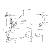
Mount knee lifter before motor installation; attach bracket A using screws.
Apply oil to specified points before operation, including hook, shaft saddle, and feed bar.
Drill holes, insert supports, attach cover, fit winder, adjust position, and secure.
Move needle bar to highest position, loosen clamp, insert needle with indented part right, tighten screw.
Raise lever to remove bobbin case; fit case into driving shaft and tilt lever to attach.
Route thread, bring winder to belt, adjust screw for winding amount, adjust tension adjuster.
Place bobbin with thread end right, pass thread through slit, under tension spring, and out notch.
Thread the machine following the numbered sequence from 1 through 13.
Turn stitch length dial to align desired value with the pin for length adjustment.
Push feed lever down for reverse stitching; machine resumes normal mode upon release.
Turn tension nut clockwise to increase, counterclockwise to decrease needle thread tension.
Turn tension screw clockwise to increase, counterclockwise to decrease bobbin thread tension.
Loosen stopper screw, move stopper to adjust stroke; right increases, left decreases.
Loosen nut, turn spring shaft counterclockwise to increase tension, clockwise to decrease.
Turn pressure spring regulator clockwise to increase, counterclockwise to decrease presser foot pressure.
Adjust operating height by loosening nut and changing cam rod boss position.
Loosen top feed crank screw, adjust stroke by moving crank left or right.
Adjust feed dog height by loosening screw and temporarily fixing, then tightening.
Determine needle bar height based on distance between needle eyelet and hook blade point.
Loosen hook driving shaft saddle screws to adjust clearance between hook blade point and needle.
Adjust needle guard to lightly contact needle side face by bending it.
Adjust lever position for 0.1-0.15mm clearance between lever and bobbin case protruding section.
Set feed dial to minimum, loosen clamp screw, adjust clearance to 7.5mm.
Set feed dial to minimum, loosen screw, align feed dog with needle hole center.
Mechanism actuates if thread is caught; reset by removing thread and turning pulley.
Turn adjustment screw to increase or decrease safety load.
Loosen screws, remove handwheel and bushing, draw feed lever shaft, remove belt.
Install belt in reverse order; adjust timing between main shaft and hook driving shaft.
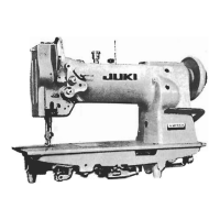
Use M type V belt; table shows relationship between pulley, belt length, and speed.
Check thread path, tension, needle-to-hook clearance, and hook condition.
Address needle tension, take-up spring, and needle-to-hook timing issues.
Check presser foot pressure, needle bar height, needle guard, needle size, and bobbin case.
| Max Stitch Length | 5 mm |
|---|---|
| Motor Type | Clutch motor |
| Type | Lockstitch |
| Lift of the Presser Foot | 13 mm |
| Hook | Full rotary hook |