Do you have a question about the Jun-Air OF301 DC motor and is the answer not in the manual?
Please read the following information and operating instructions included with this product before use.
Protect compressor against rain, moisture, frost and dust. Follow max pressure and ambient temperature limits.
Provided that the operational instructions have been carried out, your JUN-AIR compressor is guaranteed against faulty material or workmanship for 2 years.
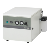
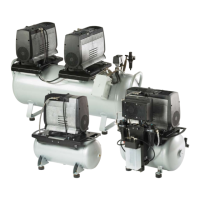
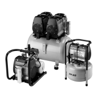
The instructions in this manual are intended for the OF300 compressors and vacuum pumps.
Your new compressor/vacuum pump should be delivered in a clean and undamaged box. If not, contact your distributor immediately.
Incorrect electrical connection may result in electric shock. Connection must follow local regulations and by qualified engineers.
To avoid the risk of electric shock, do not install the compressor in areas where it may get in contact with water or other liquids.
The compressor/vacuum pump is only suitable for atmospheric air.
A: Max. pressure adjustment (cut-out), B: Differential adjustment (cut-in).
Start vacuum - Differential vacuum = stop vacuum. The procedure below is based on the base adjustment.
Switch off and isolate from electrical supply before removing any parts. Empty air receiver of air before dismantling pressure system parts.
Common causes for compressor not starting, including power, connections, capacitor, thermal protection, and pressure.
Indicates a leaky non-return valve. Check for air leaks and clean or replace the valve.
Check piston gaskets, valve plate, or inlet cock for defects and replace if necessary.
Regular checks and maintenance procedures to ensure optimal performance and longevity of the compressor.
Details on pressure testing, application, installation, placement, corrosion protection, and safety valve for the pressure vessel.
Manufacturer's declaration that products conform to relevant EU directives.
Wiring diagram for OF301/302 compressors operating at 230V/50Hz.
Wiring diagram for OF301/302 compressors operating at 115V/60Hz.
Wiring diagram for OF301/302 compressors operating at 240V/60Hz.
Wiring diagram for OF301/302 compressors operating at 3x400V/50/60Hz.
Wiring diagram for OF301 12/24V DC models with motor protection.
Wiring diagram for OF301 12/24V DC models without motor protection.
Electrical wiring diagram for OF301/302-B(D) models operating at 100/240V / 50/60Hz.
Electrical wiring diagram for OF301V/302V models operating at 100/240V / 50/60Hz.
Electrical wiring diagram for 2xOF301/2x302-B models operating at 100/240V / 50/60Hz.
Electrical wiring diagram for 2xOF301/2x302-B(D) models operating at 100/240V / 50/60Hz.
| Brand | Jun-Air |
|---|---|
| Model | OF301 DC motor |
| Category | Air Compressor |
| Language | English |