Smart Visu Server
02.08.20232 / 40024003700
Included in scope of delivery
- Smart Visu Server including software
- Operating instructions
- Plug-in power supply
- SV-SERVER2: EU power supply (Europlug)
- SV-SERVER2-INT: Power supply, including adapter for BS (United Kingdom), EU (Europlug) and CN (China)
4 Information for electrically skilled persons
Installation and electrical connection
DANGER
Electrical shock on contact with live parts in the installation environment.
Electrical shocks can be fatal.
Before working on the device, disconnect the power and cover live parts in the area!
Installation as a desktop device
• Ax the four rubber feet (included in the scope of delivery) on the bottom of the device.
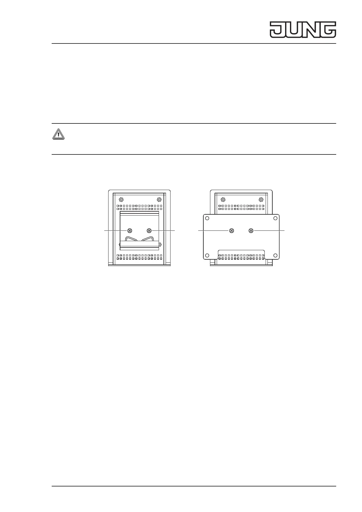
DIN rail mounting or wall installation
Fig. 2 and g. 3: DIN rail mounting or wall installation
Requirement:
Mounting set ref.-no.: SV-SERVER2-MS (available separately)
Adapter in the mounting set:
- Mounting adapter for DIN rail (g. 2)
- Adapter for wall installation (g. 3)
• Fasten the adapter on the back of the device with screws (6) from the mounting set.
• Snap the device onto the DIN rail in accordance with DIN EN 60715 or fasten it to the wall using suitable screws.
5 Operation
Status LED
The Status LED (5) displays the various operating statuses.
Flashing
yellow: Server booting
red: Error pending, server stopping
Lights up
yellow: Server and network booting
blue: Server ready, DHCP active
green: Server ready, static network address
red: Update completed, restart is initiated
Flashing
blue/magenta: Update operation, DHCP active
green/magenta: Update operation, static network address
66
6 6
 Loading...