Information about the heater
? ??? ??? ??? (YYYY/MM)
7
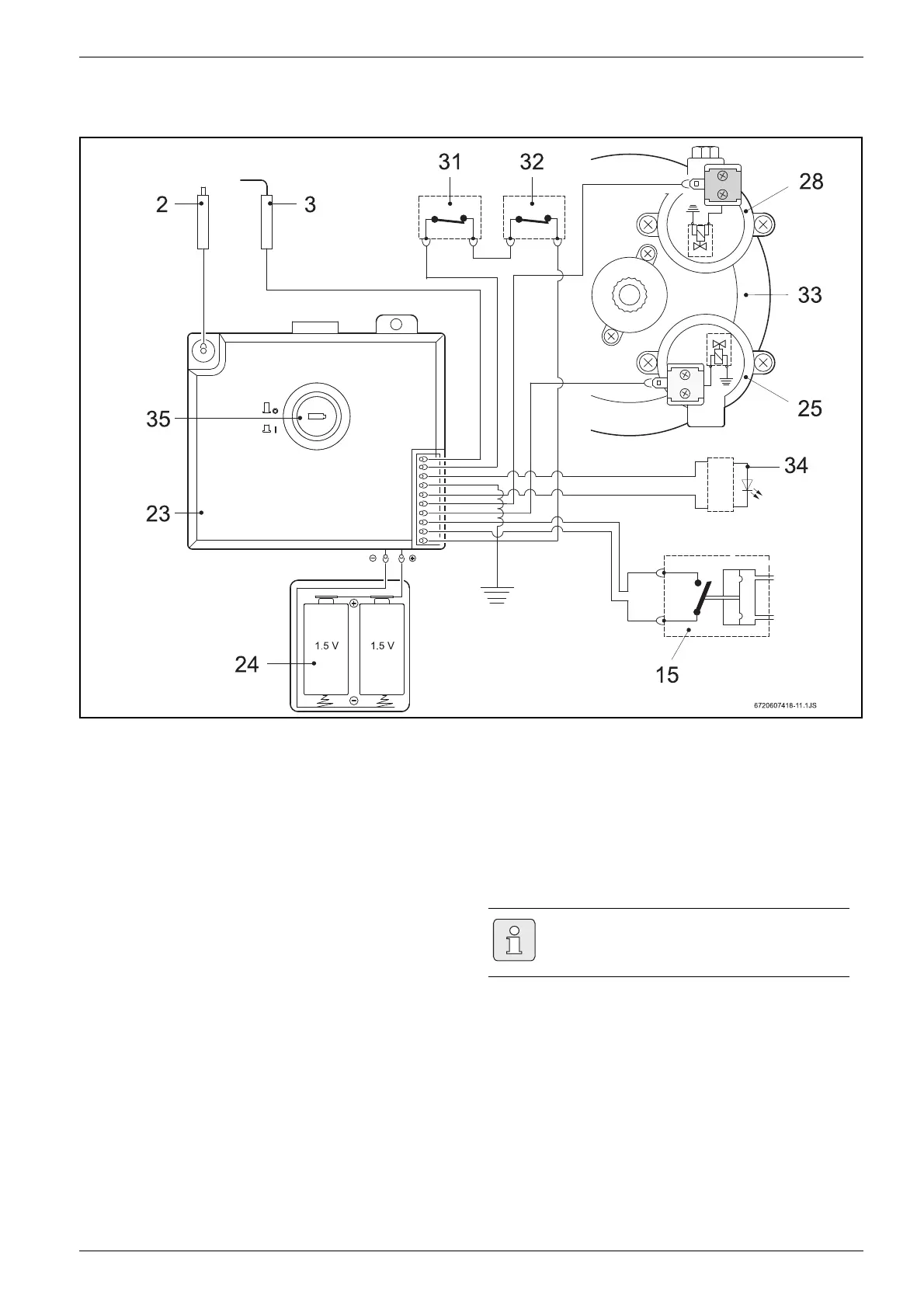
2.8 Electrical diagram
Fig. 3 Electrical diagram
2 Spark plug
3 Ionisation probe
15 Micro-switch
23 Ignition unit
24 Battery compartment
25 Servo valve (normally open)
28 Pilot valve (normally closed)
31 Temperature limiter
32 Flue gas safety device
33 Diaphragm valve
34 LED - Burner status check
35 Switch / LED - Battery status check
2.9 Function
This gas heater is equipped with automatic electronic
ignition which simplifies its operation.
B To do so, just turn on the switch (Fig. 8).
After this procedure, automatic ignition occurs when-
ever a hot water tap is opened. First, the pilot burner is
lit and approximately four seconds afterwards the main
burner. The pilot burner flame is then extinguished after
a short period of time.
This is a way of saving a great amount of energy as the
pilot burner only operates for the minimum necessary
time to ignite the main burner, in contrast to conven-
tional systems which operate permanently.
If thishappens:
B Close and open the hot water tap to repeat the igni-
tion process until all the air has been purged.
Air in the gas supply pipe when the heater
is started up may cause ignition to fail.
 Loading...