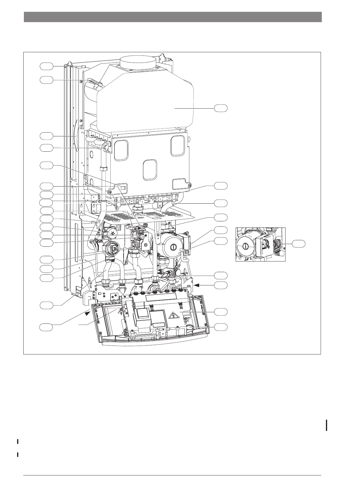
2.1.6 ZSC 18/27/28 MFK
Fig. 6
3 Testing point (injector pressure)
4 Heatronic 3
6 Temperature limiter for heat exchanger
6.1 Flue gas monitoring system (draught diverter)
6.2 Flue gas monitoring system (combustion chamber NTC)
7 Testing point for gas supply pressure
8.1 Pressure gauge
15 Safety valve (CH system)
18 Central heating pump
18.1 Pump speed selector switch
20 Expansion vessel
27 Automatic air vent
29 Burner with injector manifold
32 Flame sensing electrode
33 Igniter electrodes
36 Temperature sensor in CH flow
39 Draught diverter
43 CH flow
56 Gas valve
63 Adjusting nut for max. gas inlet flow volume
64 Adjusting screw for min. gas inlet flow volume
71 Storage flow pipe
72 Storage return pipe
84 Motor 3-way diverter valve
88 3-way valve
102 Inspection window
120 Fixing points
295 Appliance type sticker
361.1 Drain tap
418 Data plate
6 720 613 085 - 04.1O
6.1
120
20
6
102
84
88
7
64
63
33
56
3
36
11
43
39
27
18
18.1
361.1
418
8.1
4
32
29
6.2
295
15
9 | Appliance Layout and Hydralic Diagrams
6 720 660 238 (2008/07)
9
 Loading...