EasyManua.ls Logo

Juntek DPM-8624 User Manual

Default Icon
18 pages
To Next Page IconTo Next Page
Page #1 background imageLoading...
Page #1 background image
1
1
C heck
When y o u g e t a new DPM8600 series programmable highpower power
supply, i t i s recommended thaty o u check theinstrument asfollows.
1.Check fordamage caused byshipping.
Ifthepackaging carton orbubble bag protection pad i s found tobe
severely damaged, please keep i t until thewhole machine and accessories
pass thetest.
2.Check that thecontents ofthebox arecomplete.
Thecontents oftheboxareasfollows. Ifthecontent does not matchor
theinstrument i s damaged, please contact your dealer orthecompany.
H o s t : DPM8600 programmable highpower power supply *1
Accessories:
U s e r Manual *1
OptionalProgrammable power wireless r e m o t e control *1
5VU S B transfer cable *1
U s e r Manual * 1
3.Check thewhole machine.
Iftheinstrument i s found tobedamaged, theinstrument i s notworking
properly, orfails theperformance test, please contact your dealer orthe
company.
Question and Answer IconNeed help?

Do you have a question about the Juntek DPM-8624 and is the answer not in the manual?

Juntek DPM-8624 Specifications

General IconGeneral
Output Voltage0-60V
Output Current0-24A
Voltage Resolution10mV
Current Resolution10mA
Communication InterfaceUSB, RS485
Input VoltageAC 110V/220V ±10%, 50Hz/60Hz
Operating Temperature0°C to 40°C
ProtectionsOver Voltage, Over Current, Over Temperature, Short Circuit
Cooling MethodFan Cooled
DisplayLCD
Efficiency≥85%

Summary

Initial Device Check

Shipping Damage Inspection

Inspect packaging for severe damage. Keep damaged packaging until the unit and accessories are tested.

Package Contents Verification

Ensure all listed items are present. Contact dealer if contents are missing or the instrument is damaged.

Technical Specifications

Module Component Description

DPM8600 Series Module Layout

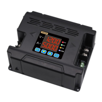
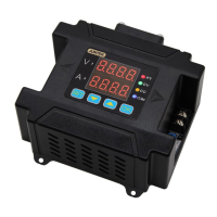
Describes the physical components of the DPM8600 series digital power supply module with labeled diagrams.

Display Information Guide

Basic Operation Instructions

Voltage and Current Adjustment

Guides on connecting input, setting voltage/current values, and turning the output on or off.

Save and Load Functionality

Accessing Save/Load and Calibration

Instructions on accessing save, load, temperature display, and calibration functions via display interface buttons.

Save and Load Operation Details

Calibration Procedures

SET Function Configuration

SET Function Configuration Options

Configuring SET Function Options

Explains how to use the SET button to access and configure functions like reset, protocol, response, and power-on status.

Voltage and Current Limits

Wireless Controller Instructions

Wireless Controller Technical Parameters

Wireless Control Panel Description

Display Information

Control Panel Operation

Setting Voltage, Current, and Output

Explains how to set voltage/current and control output using the V, A buttons, knob, and OK button.

Function Setting Menu

Function Setting Operations

Key Lock Functionality

Upper and Lower Limit Setting

Upper and Lower Limit Display Interface

Detailed Function Explanations (Part 1)

Load/Save Parameters (M1-M9)

Explains loading and saving parameters to storage locations M1 through M9.

Detailed Function Explanations (Part 2)

Upper Limit Setting

Details setting the upper limit for voltage and current, indicated by MAX.

Lower Limit Setting

Details setting the lower limit for voltage and current, indicated by MAX.

Related product manuals