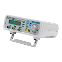
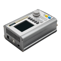
The MHS5200A series of instruments are advanced dual-channel function/arbitrary waveform signal generators designed for a wide range of applications in electronics, scientific research, and production lines. These instruments leverage large-scale FPGA integrated circuits and high-speed MCU microprocessors, employing surface mount technology for enhanced anti-interference capabilities and extended service life. The user interface features an LC1602 liquid crystal display, which provides a clear two-line readout: the upper line shows the current frequency, while the lower line displays other variable parameters or functions, easily navigable via page keys for improved operability.
Function Description
The MHS5200A series excels in signal generation, waveform sweeping, and parameter measurement. It offers two independent output channels that can operate synchronously with adjustable phase differences, making it suitable for applications requiring precise timing and phase control. The instrument includes both linear and logarithmic frequency sweep functions, with sweep times configurable up to 999 seconds.
A comprehensive set of basic function waveforms is available, including sine wave, triangle wave, square wave, rising sawtooth, falling sawtooth, and pulse wave with adjustable duty cycle. Beyond these, users can define and store up to 16 groups of arbitrary waveforms, providing extensive flexibility for custom signal generation.
The device features 10 sets of parameter storage locations (M0-M9), with M0 automatically loaded upon power-on, ensuring quick access to frequently used configurations. A built-in precision -20dB attenuator allows for fine amplitude control, achieving a minimum amplitude resolution of 1mV. The instrument also incorporates a DC bias function, adjustable from -120% to +120%, and precise pulse wave duty cycle adjustment accurate to 0.1%.
For measurement capabilities, the MHS5200A includes functions for frequency, period, positive and negative pulse width, and duty cycle measurement, as well as a counter. Users can select from four frequency measurement gate times to balance speed and accuracy. All parameters can be calibrated through internal procedures, ensuring high precision.
The powerful communication function and fully open communication protocol simplify secondary development, allowing the instrument to be controlled via PC. Arbitrary waveforms can be edited on a PC and then downloaded to the instrument for output. An optional power module can be equipped to achieve a signal output amplitude of up to 40Vpp and a maximum output current of 1A.
Important Technical Specifications
Model Variations:
- MHS-5206A: Sine wave output maximum frequency 6MHz
- MHS-5212A: Sine wave output maximum frequency 12MHz
- MHS-5220A: Sine wave output maximum frequency 20MHz
- MHS-5225A: Sine wave output maximum frequency 25MHz
Frequency Characteristics:
- Sine wave frequency range: 0~6MHz (MHS-5206A), 0~12MHz (MHS-5212A), 0~20MHz (MHS-5220A), 0~25MHz (MHS-5225A)
- Square wave frequency range: 0~6MHz
- Pulse wave frequency range: 0~6MHz
- TTL / COMS digital signal frequency range: 0~6MHz
- Arbitrary / other waveform frequency range: 0~6MHz
- Frequency minimum resolution: 10mHz
- Frequency error: ±5x10⁻⁶
- Frequency stability: ±1x10⁻⁶/5 hours
- Arbitrary / other waveform: 50Ω±10%
Amplitude Characteristics:
- Amplitude range (peak-to-peak value): 5mVp-p~20Vp-p
- Amplitude resolution: 1mVp-p (-20dB attenuation), 10mVp-p (No attenuation)
- Amplitude stability: ±0.5% (Each 5 hours)
- Amplitude error: ±1%+10mV (Frequency 1KHz, 15Vp-p)
- Offset range: -120%~+120%
- Offset resolution: 1%
- Relative range: 0~359°
- Phase resolution: 1°
Waveform Characteristics:
- Waveform types: Sine, Square, Pulse (adjustable duty cycle, precise adjustment of pulse width and period), Triangular wave, Partial sine wave, CMOS wave, DC level (set DC amplitude by adjusting offset), Half wave, Full Wave, Positive staircase wave, Anti-ladder wave, Noise wave, Exponential rise, Exponential drop, Symplectic pulse and Lorenz pulse, and 60 arbitrary waveforms.
- Wave length: 2048 points
- Waveform sampling rate: 200MSa/s
- Waveform vertical resolution: 12 bits
- Sine wave harmonic suppression: ≥40dBc (<1MHz); ≥35dBc (1MHz~25MHz)
- Total harmonic distortion: <0.8% (20Hz~20kHz)
- Square wave rise and fall time: ≤20ns
- Square wave overshoot: ≤10%
- Square wave duty cycle adjustment range: 0.1%-99.9%
- TTL signal output level: ≥3Vpp
- TTL signal fan-out coefficient: ≥20TTL
- TTL signal rise and fall time: ≤20ns
- COMS signal low level: <0.3V
- COMS signal high level: 1V~10V
- COMS signal rise and fall time: ≤20ns
- Sawtooth wave duty cycle >50%: Sawtooth wave
- Sawtooth wave duty cycle <50%: Sawtooth wave
- Arbitrary wave quantity: 16 groups
- Arbitrary wave storage depth / group: 1KB / 16 groups
Frequency Measurement Range:
- GATE-TIME=10S: 0.1Hz-60MHz
- GATE-TIME=1S: 1Hz-60MHz
- GATE-TIME=0.1S: 10Hz-60MHz
- GATE-TIME=0.01S: 100Hz-60MHz
- Input voltage range: 0.5V-pp~20Vp-p
- Counting range: 0~4294967295
- Counting method: Manual
- Positive and negative pulse width measurement: 10ns resolution, maximum measurement 10s
- Period measurement: 20ns resolution, maximum measurement 20s
- Duty cycle measurement: 0.1% resolution, measuring range 0.1% ~ 99.9%
- Source selection: EXT.IN input (AC signal), TTL_IN input (digital signal)
Communication Characteristics:
- Interface method: USB to serial interface
- Communication rate: 57600bps
- Protocol: Command line, open agreement
General:
- Power supply: DC 5V±0.5V
- Dimension: 18019072mm
- Net weight: 550g (Host) 480g (Annex)
- Gross weight: 1090g
- Working environment: Temperature: -10℃~50℃, Humidity <80%
Usage Features
The MHS5200A is designed for ease of use with its intuitive LC1602 display and flexible page key navigation.
- Dual-Channel Operation: Both channels can work synchronously with adjustable phase differences, ideal for differential or phase-sensitive applications.
- Waveform Generation: Users can select from a variety of standard waveforms or create and store up to 16 custom arbitrary waveforms. The output waveform type can be quickly adjusted using the
OUT/OK key or by combining SHIFT+WAVE/PgUp and the ADJUST knob.
- Frequency Adjustment: The frequency can be precisely set by moving the cursor with
CH1/2/◄ or SET/► and rotating the ADJUST knob. The display unit (Hz, kHz, MHz) can also be switched.
- Amplitude Control: Amplitude (peak-to-peak value) is adjustable, with a maximum of 20Vpp (below 12MHz) or 15Vpp (above 12MHz). A -20dB attenuator allows for finer control down to 1mV resolution. Amplitude adjustment is accessed via
SHIFT+AMPL/PgDn.
- DC Offset: The DC offset can be adjusted from -120% to +120% to position the waveform relative to the ground.
- Duty Cycle Adjustment: For pulse and square waves, the duty cycle can be precisely adjusted from 0.1% to 99.9%.
- Phase Difference: The phase difference between CH1 and CH2 can be set from 0° to 359° with 1° resolution, particularly useful when tracking is enabled.
- Tracking Function: CH2 can track CH1's frequency, amplitude, and duty cycle, simplifying synchronized dual-channel operations.
- Frequency Sweep: Supports both linear and logarithmic frequency sweeps with adjustable start/stop frequencies and sweep times (1-500 seconds).
- Burst Function: Allows CH2 to burst the CH1 channel output, where CH2's cycle triggers CH1 to output a pulse wave. This requires CH1's frequency to be greater than CH2's.
- 4 TTL Outputs: Provides four TTL outputs (TTL1, TTL2, TTL3, TTL4) that can be synchronized with CH1 and CH2, with duty cycles determined by the respective channels. When CH1 and CH2 are synchronized, all TTL outputs synchronize simultaneously.
- Measurement Functions: Capable of measuring frequency, period, positive/negative pulse width, and duty cycle of external signals (AC via EXT.IN, digital via TTL.IN). Gate time selection allows balancing measurement speed and accuracy.
- Parameter Storage/Recall: 10 memory locations (M0-M9) are available to save and load instrument parameters, enhancing workflow efficiency.
- Reverse Function: Quickly reverses the output waveform phase by 180 degrees.
- PC Software Control: The instrument can be controlled via PC software, which also allows for editing and downloading arbitrary waveforms. Installation instructions and communication protocols are provided.
Maintenance Features
- Robust Design: Utilizes large-scale FPGA and MCU with surface mount technology for improved anti-interference and extended service life.
- Ventilation: Requires adequate ventilation to prevent overheating and damage. Regular inspection of air outlets and fans is recommended.
- Environmental Considerations: Designed for operation in dry environments with temperatures between 10℃ and 50℃ and humidity below 80%. Avoid wet or explosive atmospheres.
- Cleanliness: Keep instrument surfaces clean and dry to prevent dust or moisture from affecting performance.
- Electrostatic Discharge Protection: Operate in an ESD-protective environment and ground cables before connections to prevent static damage.
- Handling Precautions: Handle with care during transportation to avoid damage to physical components.
- No User-Serviceable Parts: The instrument should not be disassembled by users, as this voids the warranty. Repairs and adjustments must be performed by JUNTEK authorized personnel.
- Pre-Calibrated: Machines are factory-calibrated. If self-calibration is needed, consult the manufacturer.
- Documentation and Support: Comprehensive user manuals, operation demo videos, PC software, and communication protocols are available on the JUNTEK website for support and troubleshooting.