Chapter 3: Installation
12 J100 Hardware Manual
3 Connect power
For power consumption see the specifications for each J100 model in Chapter 2, Compact Video Wall
Processors, on page 5.
a Plug the power cable in the rear power connector of the J100 unit
b Plug the other end of the power cable to a surge suppressing power strip which is connected
to a grounded outlet.
4 Power on the J100 unit
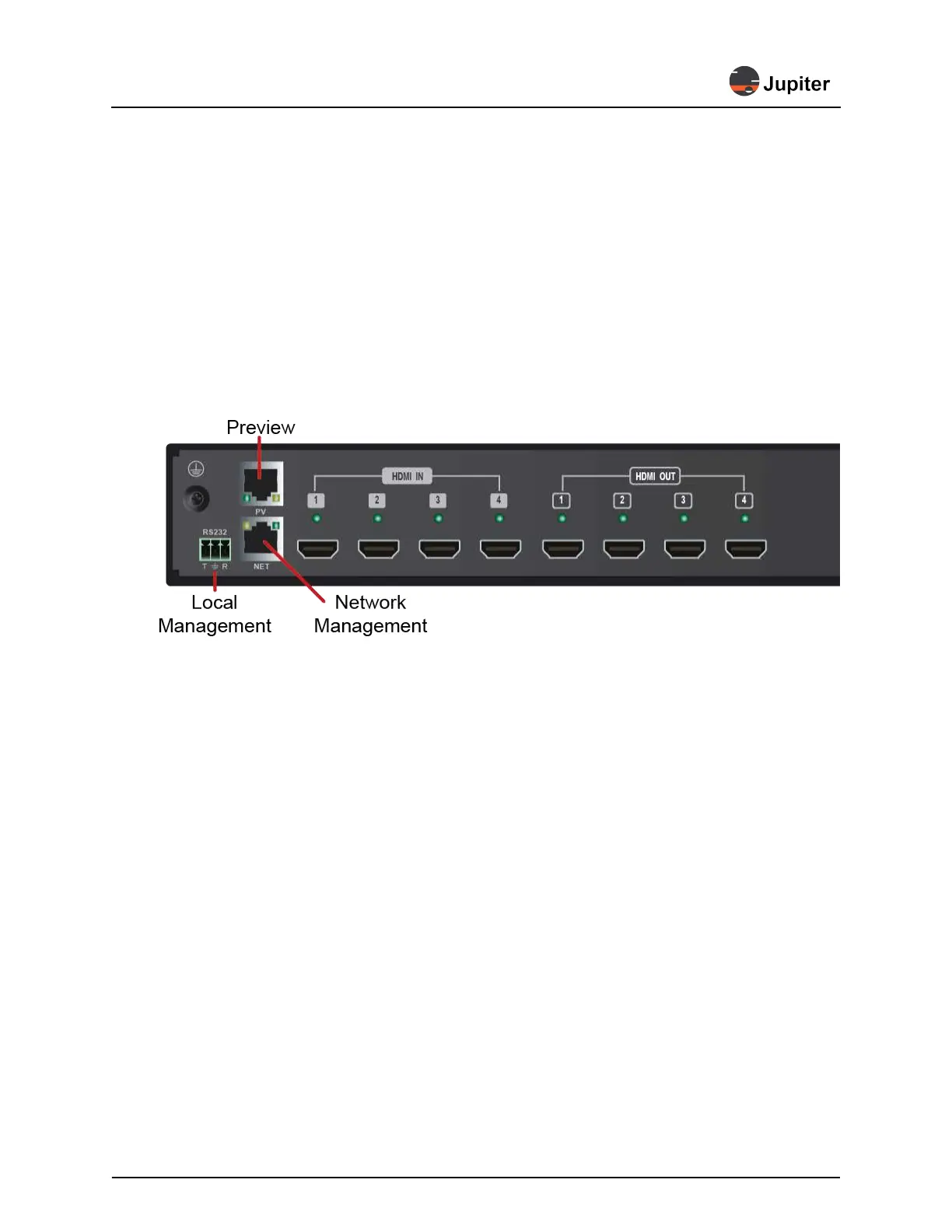
5 Connect to management
The J100 may be managed locally through a serial connection or via the network through an Ethernet
connection. Preview models have a separate Ethernet connection for supplying the preview stream to
the JVWC software.
Figure 3.1: Management and Preview Ports
a Connect Network Management
Connect RJ45 Ethernet cable (cable supplied) to the NET port and the network
b Connect Local Management (if needed)
Connect 3P-DB9 cable (cable supplied) to the RS232 port and to the PC (via DB-9 to USB cable,
cable not supplied)
c Connect Preview (for -PV units)
Connect RJ45 Ethernet cable to the NET port and the network
6 Connect video stream sources and outputs
a Connect video stream sources to the HDMI input
b Connect the J100 outputs to the display monitors
Typically the outputs from the J100 are mapped to monitors in a pattern which mimics the display
(hence the name Mimic for the view of the view wall within Jupiter’s VWC software). To mimic the
display wall and follow the same pattern in Mimic for a 2x2 wall you would have HDMI output 1 con-
nect to the upper left display, HDMI output 2 to the upper right, HDMI output 3 to the lower left and
HDMI output 4 to the lower right.