EasyManua.ls Logo

Just Motion Control iHSS57 Series - User Manual

Just Motion Control iHSS57 Series
21 pages
Print Icon
To Next Page IconTo Next Page
Loading...
iHSS57-XX
Integrate Stepper Servo Motor
Manual
Shenzhen Just Motion Control Electro-mechanics Co., Ltd
TEL:+86-0755-26509689
FAX:+86-0755-26509289
www.jmc-motion.com
Email:info@jmc-motion.com
Address: Floor2, Building A, Hongwei Industrial Zone No.6,
Liuxian 3rd Road, Shenzhen. China
Question and Answer IconNeed help?

Do you have a question about the Just Motion Control iHSS57 Series and is the answer not in the manual?

Summary

Overview

Features

Ports Introduction

ALM Signal Output Ports

Describes ALM and PED signal output terminals for alarm and position feedback.

Control Signal Input Ports

Details ENA, DIR, and PUL signal input terminals for motor control.

Technological Index

Connections to Control Signal

Common Anode Connections

Illustrates wiring for common anode control signal configuration.

Common Cathode Connections

Illustrates wiring for common cathode control signal configuration.

Differential Signal Connections

Illustrates wiring for differential signal control input.

232 Serial Communication Interface

Details pin definitions for RS232 serial communication.

Control Signal Sequence Chart

Shows the timing requirements for PUL, DIR, and ENA signals.

DIP Switch Setting

Micro Steps Setting

Explains how to set micro-stepping using DIP switches SW1-SW4.

Activate Edge Setting

Describes how SW5 sets the activate edge (rising/falling) of the input signal.

Running Direction Setting

Explains how SW6 controls the motor's running direction (CW/CCW).

Faults alarm and LED flicker frequency

Fault Descriptions

Lists fault conditions corresponding to LED flicker frequencies.

Appearance and Installation Dimensions

Parameter Setting

Parameter Table

Lists motor parameters, definitions, ranges, and default values.

Parameter Descriptions

Details the function and effect of various motor parameters.

Processing Methods to Common Problems and Faults

Power on power light off

Troubleshooting steps for when the power light is off upon startup.

Power on red alarm light on

Troubleshooting steps for a red alarm light during startup.

Red alarm light after motor running

Troubleshooting steps for red alarm light after minor motor movement.

Motor not running after input pulse

Troubleshooting steps for when the motor does not run after receiving pulse signals.

Overview

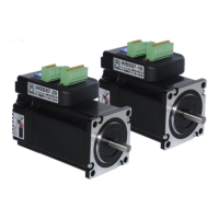
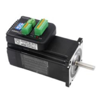
The iHSS57-XX Integrate Stepper Servo Motor is a merged stepper servo driver and motor system, combining the advantages of both stepper and servo drives. This product integrates servo control technology into a digital stepper drive, utilizing an optical encoder with a high-speed position sampling feedback of 50 μs. This allows for immediate correction of any position deviation, ensuring high accuracy. The system is designed to offer lower heat generation, reduced vibration, and fast acceleration, making it suitable for various motion control projects.

Function Description:

The iHSS57-XX operates as an integrated stepper servo motor, meaning the motor and its driver are combined into a single compact unit. This integration simplifies installation and saves mounting space. It employs closed-loop control, which is a key feature of servo systems, to prevent step loss, a common issue with open-loop stepper motors. The optical encoder continuously monitors the motor's position and provides feedback to the driver. If the actual position deviates from the commanded position, the driver immediately adjusts the motor's current to correct the error, ensuring precise positioning.

The device supports various control signal input methods, including common anode, common cathode, and differential signals, offering flexibility in integration with different control systems. It also features a 232 serial communication interface for parameter setting and monitoring, typically through a HISU adjuster.

The motor's running characteristics are enhanced by internal accelerate and decelerate control, which significantly improves the smoothness of starting and stopping. This feature helps to reduce mechanical stress and improve overall system performance.

Important Technical Specifications:

  • Input Voltage: 24~50VDC (36V Typical)
  • Output Current: 4.5A 20KHz PWM
  • Pulse Frequency Max: 200K
  • Communication Rate: 57.6Kbps
  • Protection Features:
    • Over current peak value: 8A±10%
    • Over voltage value: 80V
    • Over position error range: Can be set through the HISU
  • Environment Specifications:
    • Operating Temperature: 70℃ MAX
    • Storage Temperature: -20°C~+65°C
    • Humidity: 40~90%RH
    • Cooling Method: Natural cooling or forced air cooling
    • Environment: Avoid dust, oil fog, and corrosive gases
  • Motor Models and Lengths:
    • iHSS57-36-10-XXX: 85 mm
    • iHSS57-36-20-XXX: 106 mm

Usage Features:

  • Integrated Compact Size: The combined motor and driver design saves mounting space and simplifies wiring.
  • No Step Loss: The closed-loop control ensures that the motor maintains its commanded position, even under varying loads, eliminating step loss.
  • High Accuracy in Positioning: The 50 μs position sampling feedback and immediate error correction contribute to high positioning accuracy.
  • 100% Rated Output Torque: The motor can consistently deliver its full rated torque.
  • Variable Current Control Technology: This technology optimizes current usage, leading to high current efficiency.
  • Small Vibration, Smooth and Reliable Moving at Low Speed: The advanced control algorithms minimize vibration, especially at low speeds, ensuring smooth and reliable motion.
  • Accelerate and Decelerate Control Inside: Built-in acceleration/deceleration profiles improve the smoothness of motor starts and stops.
  • User-Defined Micro Steps: Micro-stepping resolution can be configured via DIP switches or through the serial communication interface (HISU). The DIP switch settings offer a wide range of micro-step options from 800 to 40000 steps per revolution, plus a default setting.
  • No Adjustment in General Applications: For most typical uses, the default parameters are sufficient, reducing the need for complex tuning.
  • LED Indicators: A green light indicates normal running, while a red light signifies protection mode or an offline state, providing quick visual status feedback.
  • DIP Switch Settings:
    • Micro Steps Setting (SW1-SW4): Allows selection of various micro-step resolutions (e.g., 800, 1600, 3200, 6400, 12800, 25600, 51200, 1000, 2000, 4000, 5000, 8000, 10000, 20000, 40000). The internal default micro steps are active when SW1-SW4 are all "on."
    • Activate Edge Setting (SW5): Determines whether the input signal's active edge is rising ("off") or falling ("on").
    • Running Direction Setting (SW6): Sets the motor's running direction to CCW ("off") or CW ("on").
  • Control Signal Sequence Chart: Specific timing requirements for PUL, DIR, and ENA signals must be adhered to to avoid fault operations and deviations. For example, ENA must be ahead of DIR by at least 5 μs, and DIR must be ahead of PUL active edge by 6 μs. Pulse and low-level widths must be at least 2.5 μs.
  • Parameter Setting (via HISU): The drive offers 20 configurable parameters (P1-P20) accessible through a 232 serial communication interface and a HISU adjuster. These parameters include current loop Kp/Ki, damping coefficient, position loop Kp/Ki, speed loop Kp/Ki, open/close loop current, alarm level, stop lock enable, enable signal level, arrival level, position error limit, and user-defined p/r. Default values are provided, but specific applications may require fine-tuning.

Maintenance Features:

The manual provides a section on "Processing Methods to Common Problems and Faults," which serves as a basic troubleshooting guide:

  • Power on power light off:
    • Check for power input and power supply circuit.
    • Verify input voltage is not too low.
  • Power on red alarm light on:
    • Check motor feedback signal and motor connection to the drive.
    • Verify input voltage is within the acceptable range (not over or under voltage).
  • Red alarm light on after the motor running a small angle:
    • Check motor phase wire connections.
    • Verify motor poles and encoder lines parameters in the drive match the real parameters.
    • Check if the pulse signal frequency is too fast, potentially causing the motor to exceed its rated speed and lead to a position error.
  • After input pulse signal but the motor not running:
    • Check the reliability of input pulse signal wire connections.
    • Ensure the input pulse mode corresponds to the real input mode.

These troubleshooting steps help users diagnose and resolve common issues, minimizing downtime and ensuring the continued operation of the iHSS57-XX system. The detailed parameter descriptions also aid in understanding the impact of various settings on motor performance, facilitating advanced tuning and optimization.

Just Motion Control iHSS57 Series Specifications

General IconGeneral
BrandJust Motion Control
ModeliHSS57 Series
CategoryEngine
LanguageEnglish