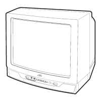
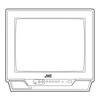
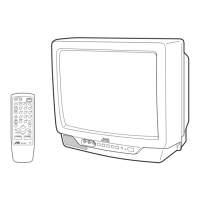
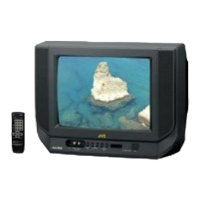
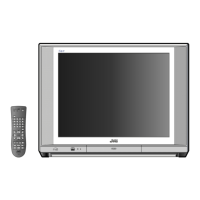
No. 52029
V-14A3
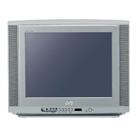
V-1415EE
V-14AMG3
8
SPECIFIC SERVICE INSTRUCTIONS
DISASSEMBLY PROCEDURE
REMOVING THE REAR COVER
1. Unp lu g t he po we r plu g.
2. As sh own in f igure, remove t he 5 screws marked
!
!!
!
an d a
screw marked "
""
".
3. W ithdr a w t he rear co ver to ward you.
[CAUTION]
"
When r einst allin g th e re ar cove r , c arefu lly pus h it inward af ter
insertin g t he MA IN PWB int o th e rea r cover gr oo ve .
REMOVING THE MAIN PW BOARD
" After removing the rear cover.
1. Slight ly ra is e th e b ot h side s of t he MAIN PW BOARD b y han d
an d re mo ve t he PWB stop per marked #
##
# from the front cabinet.
2. W ithdr a w t he MAIN PW B OARD b ackward.
(If n ecess ary, take off the wire clam p, c onnect ors etc. )
REMOVING THE SPEAKER
"
After removing the rear cover.
1. By holding up t he SP EAK ER HOLDER m ar ked
$
$$
$
slightly and
un locking th e claw, t he SP EAK ER HOLDE R can b e removed .
The n yo u c an r e mo ve t he SPE AKE R.
CHECKIN G THE MAIN PW BOARD
1. To ch eck the ba ck side of th e PW B oard.
1) Pu ll out the MA IN PW Bo ard. (Ref er to RE MO VING THE MAIN
PW B oard)
2) Erect th e PW Board ve rt ic ally so that you ca n easily ch eck th e
b ack side of th e PW B oard.
[CAUTION]
"
When e recting th e PW Board, be car ef ul s o t hat th ere will b e n o
con tact ing with ot her PW Board.
"
Before turning on power, make sure that the CRT earth wire and
oth er conne cto r are p rope rly c onnect ed.
WIRE CLAMPING AND C ABLE T YING
1. Be sure t o clamp th e wire.
2. Never remo ve th e c able tie use d f or tying th e wire s to ge ther.
Sh ould it be inad ver te ntly r emove d, b e su re to tie th e wires wit h a
new cable tie.