No. 52029
V-14A3
V-1415EE
V-14AMG
27
DEFLECTION CIRCUIT ADJUSTMENT
"
The re are 2 mod es of adju stment (s ettin g va lue) ---- --
①
50 Hz mod e an d
②
6 0Hz mod e - -- - - de pe ndin g u po n th e kind of s igna ls
(vertic al freq ue ncy 50Hz / 60Hz).
"
When ad juste d in mod e ① , mode ② will be automatically set.
The setting (adjustmen t) usin g the REMOTE CONTROL UNIT is made on the basis of the initial setting values.
The setting values which adjust the screen to the optimum condition can be different fr om the initial setting values.
Item
Measuring
instrument
Test point Ad justment part Description
Ad ju st ment
of
V.HEIG HT
&
V. POSITI ON
Signal
generator
Remote
control unit
1. VE R. POS ITION
3. VE R. HE IG HT
1. Input a circle p att ern sign al.
2. En ter th e SERVICE MENU.
3. Select 3. DEF. f rom SERVICE ME NU.
4. Select 1. VER. POS ITION with the MENU
▼
/
▲
key.
5. Set the initial setting value with the MENU - / + key.
6. Adjust V and V’ to be equal with the MENU - / + key as shown in
Fig.2.
7. Input a cross -h atch sign al.
8. Select 3. V . HEIGHT with the MENU
▼
/
▲
key.
9. Set the initial setting value with the MENU - / + key.
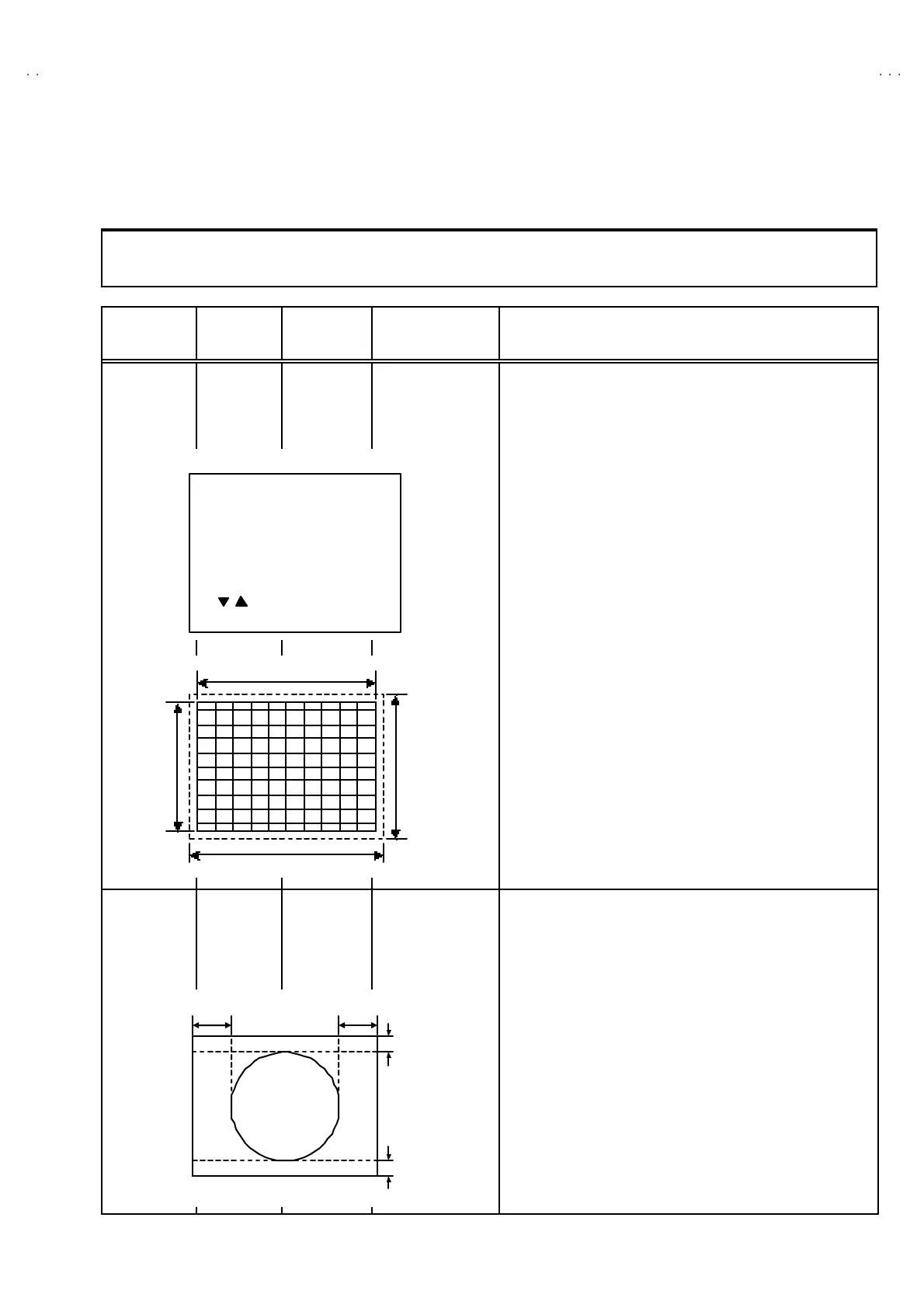
10. As shown in Fig.1, adjust VE R. HE IGH T and mak e th e ver tical
screen size 92% of the pictu re size with t he MENU - / + ke ys of
remote control unit.
Ad ju st ment
of
HOR .
POSITION
Signal
generator
Remote
control unit
2.HOR. POSITION 11. Input a circle pattern signal.
12. Sele ct 2. HOR POSITION with the MENU
▼
/
▲
key.
13 . Se t th e initia l sett ing value of 2. HOR. POSITION with the
MENU - / + key.
14. Adju st 2. HOR. POSIT ION to make H= H" as sh own in Fig. 2
with the MENU - / + ke y.
Screen size
Picture size 1 00%
Screen
size
92%
Picture
size
10 0%
Fig.1
HH"
Fi
.2
V
V'
DEF
- / + : OPERATE DISP : EXIT
**
/ :SELECT
50Hz
1. VER. POSITI ON
PAL
 Loading...