No.51709
V-28BD5EKI AV-28BD5EP AV-28BD5EE
V-28BD5EKIS AV-28BD5EPS AV-28BD5EES
1-11
ADJUSTMENTS
+B VOLTAGE CHECK
1. Receive the standard colour bar signal.
2. Connect digital voltmeter between + of B1 Line circuit and GND.
3. Confirm that voltage is DC 142V
#
2.0V.
SCREEN
1. Set TV in AV mode without video signal
⇒
Black screen.
2. Set [WP Red], [WP Green] and [WP Blue] equal to “32”.
3. Set [Black R], [Black G] equal to “8”.
4. Set TV in normal I mode.
5. Adjust SCREEN VR (on FBT) such that the highest cathode cut-off voltage measured on CRT SOCKET PWB ASS’Y is DC 140V
±
5V.
WHITE BALANCE
NOTE
:
Confirm SCREEN Adjustment has been adjusted.
■
■■
■
LOW LIGHT
1. Input the 10-step gray scale signal. (include 10% Black)
2. Enter the SERVICE MODE.
3. Turn the SCREEN VR (on FBT) gradually, to where the 2nd gray bar(10% Black) faintly visible.
4. Adjust [Black B] and [Black R] not to the colours on the gray bar.
■
■■
■
HIGH LIGHT
5. Apply the white signal.
6. Adjust [R DRIVE] and [G DRIVE] so that the picture becomes white.
FOCUS
1. Input the crosshatch pattern signal.
2. Adjust the FOCUS VR (on FBT) to have the best resolution on screen.
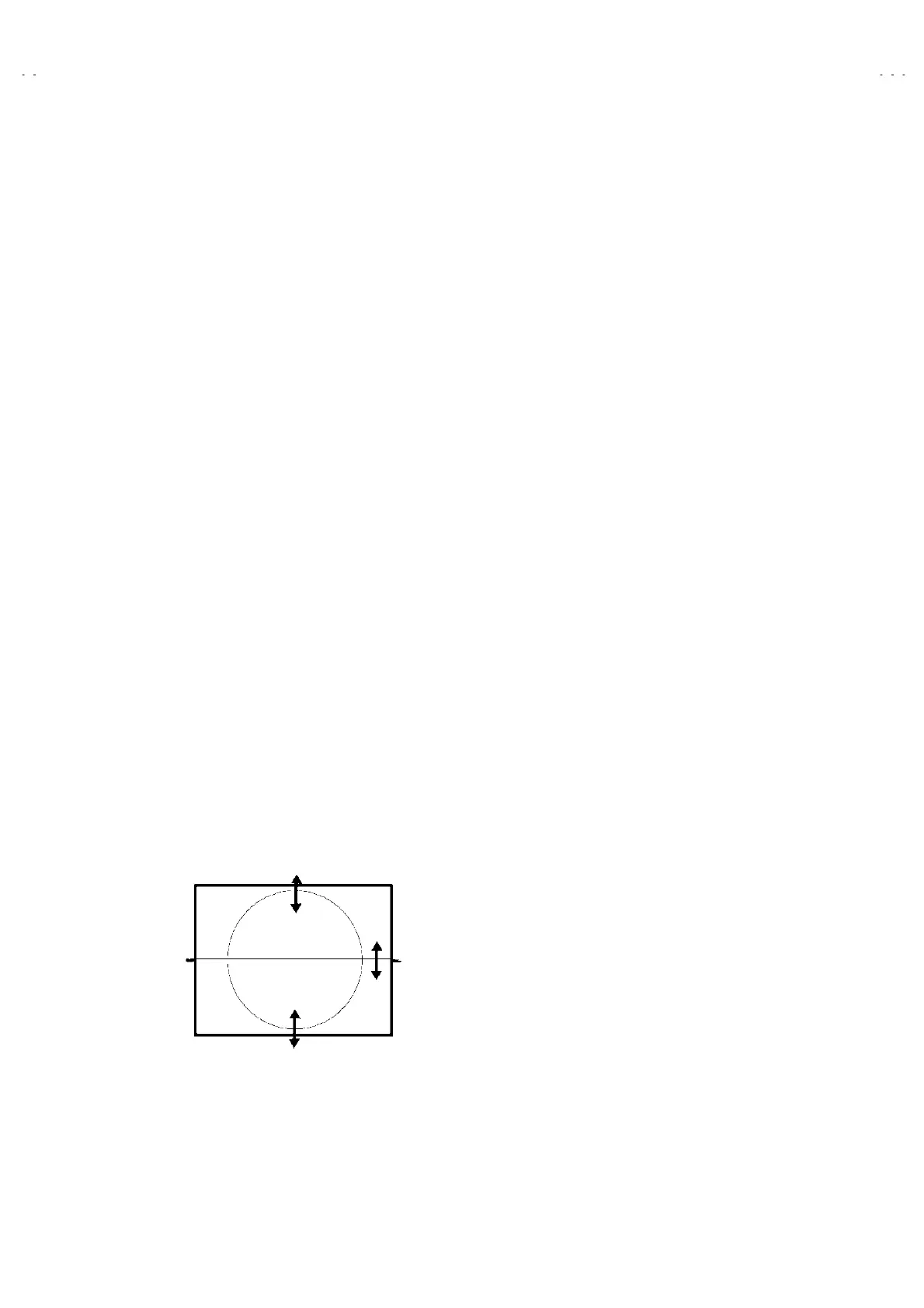
VERTICAL GEOMETRY
Adjust [V Amp], [V Shift] and [V Slope], [V Slope] [V S Cor] to compensate for vertical distortion.
HORIZONTAL PICTURE CENTERING
Adjust [H Shift] to have the picture in the center of the screen.