No. 51686
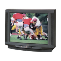
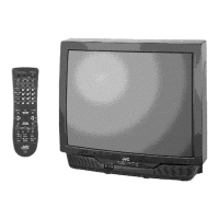
V-27D201
V-32D201
10
MEMORY IC REPLACEMENT
1. Memory IC
This model uses a memory IC.
This memory IC stores data for proper operation of the video and deflection circuits.
When replacing, be sure to use an IC written with the initial values of data.
2. Memory IC replacement procedure
Procedure Screen display
(1) Power off
Switch off the power and disconnect the power plug from the wall outlet.
(2) Replace the memory IC
Be sure to use memory ICs written with the initial data values.
(3) Power on
Connect the power plug into the wall outlet and switch on the power.
(4) System constant check and setting
It must not adjust without signal.
1) Press the
SLEEP TIMER
key and set
SLEEP TIMER
for
0 min
.
2) Before disappear the display of SLEEP TIMER settings, simultaneously
press the
DISPLAY
key and
VIDEO STATUS
key of the remote control
unit.
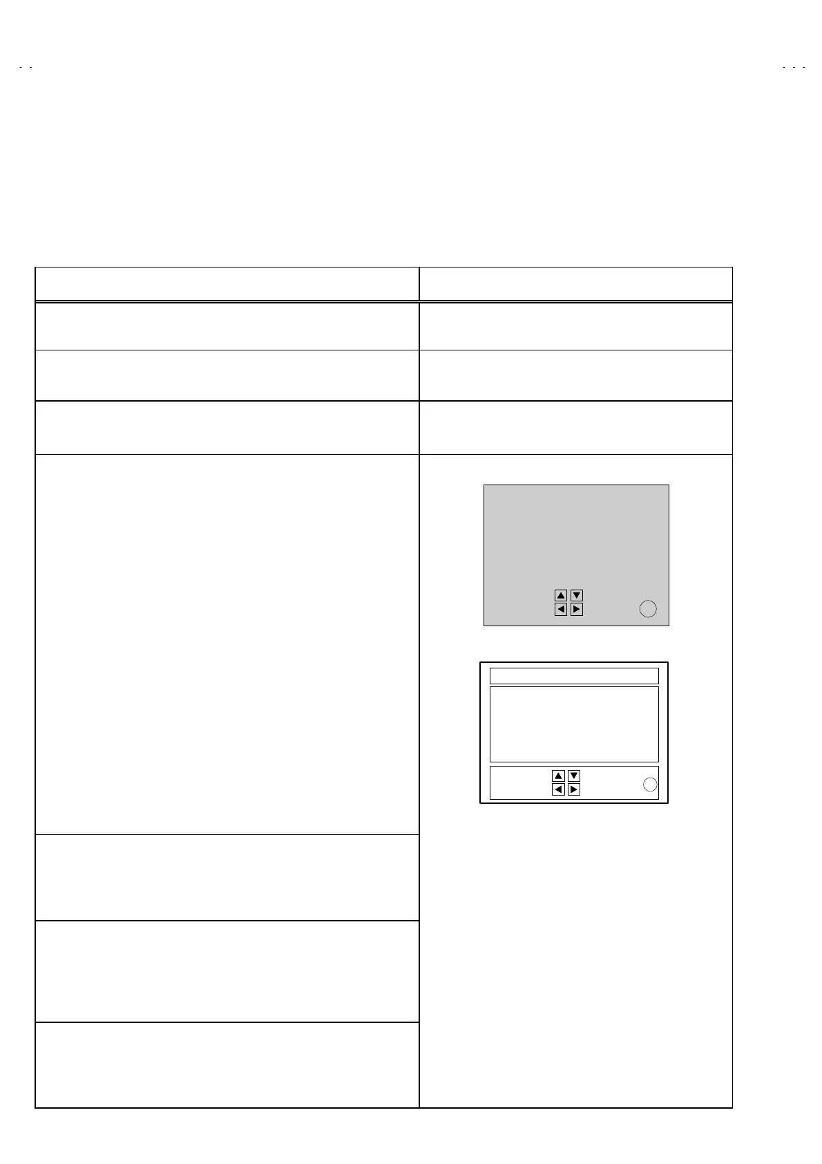
3) The SERVICE MENU screen of Fig.1 will be displayed.
4) While the SERVICE MENU is displayed, again simultaneously press
the
DISPLAY
and
VIDEO STATUS
keys to display the SYSTEM
CONSTANT screen in Fig.2.
5) Refer to the SYSTEM CONSTANT table and check the setting items. If
the value is different, select the setting item with the MENU UP/DOWN
key and adjust the setting with the MENU LEFT/RIGHT keys. (The
letters of the selected item are displayed in yellow.)
6) After adjusting, release the MENU LEFT/RIGHT key to store the setting
value.
7) Press the EXIT key twice to return the normal screen.
(5) Receive channel setting
Refer to the OPERATING INSTRUCTIONS (USER'S GUIDE) and set
the receive channels (Channels Preset) as described.
(6) User settings
Check the user setting items according to Table 2.
Where these do not agree, refer to the OPERATING INSTRUCTIONS
(USER'S GUIDE) and set the items as described.
(7) SERVICE MENU setting
Verify what to set in the SERVICE MENU, and set whatever is necessary
(Fig.1).For setting, refer to the SERVICE ADJUSTMENT.
EX
IT
EXIT BY
SERVICE MENU (MAIN MENU)
SERVICE MENU
PICTURE SOUND
THEATER OTHERS
LOW LIGHT HIGH LIGHT
RF AFC
VCO
CW
I2C BUS CTRL
SELECT BY
OPERATE BY
Fig.1
SYSTEM CONSTANT
MODEL :
CCD :YES
V-CHIP :YES
CAN V-CHIP :NO
MN
SELECT BY
OPERATE BY EXIT BY
EX
IT
Fig.2
 Loading...