Do you have a question about the JVC AV-32D201 and is the answer not in the manual?
Details of the JVC RM-C383 remote control unit's functions and layout.
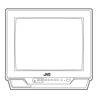
Explains the front panel and terminal layout of the JVC TV.
Details the rear panel connections and ports for the JVC TV.
Lists the function of each button on the JVC RM-C383 remote control.
Detailed steps for disassembling various components of the JVC TV.
Instructions for checking boards, wire clamping, and cable tying during service.
Safety precautions and recommended tools for chip component replacement.
Step-by-step guide for removing and installing chip components.
Explanation of the memory IC's role in TV operation.
Step-by-step guide for replacing the memory IC and subsequent system adjustments.
Important preliminary steps and precautions before performing service adjustments.
List of necessary measuring instruments for service adjustments.
Comprehensive list of all adjustable items on the JVC TV.
Guide to operating the JVC TV's SERVICE MENU for adjustments.
Key operations for entering, exiting, and selecting items within the SERVICE MENU.
Performing adjustments for THEATER, LOW LIGHT/HIGH LIGHT, RF AFC, and VCO(CW) modes.
Procedures for adjusting B1 power supply, IF VCO, and RF AGC circuits.
How to adjust the focus for a clear picture.
Adjusting vertical center/size and horizontal position/size/side pin for screen geometry.
Adjusting white balance for low and high light conditions.
Adjusting sub color, contrast, tint, and demodulation ratio for picture quality.
Procedures for checking MTS input level and filter settings.
Adjusting MTS stereo and SAP VCOs for correct frequencies.
Steps for adjusting CRT purity using magnets and deflection yoke.
Performing static and dynamic convergence adjustments for screen alignment.
Explains abbreviations for electronic components and their tolerance codes.
Parts list for the exploded view of the AV-27D201 model.
Parts list for the exploded view of AV-32D201 models.
Parts list for the main printed wiring board assembly of the AV-27D201.
Parts list for the CRT socket printed wiring board.
Parts list for the front control printed wiring board.
Parts list for the AV selector printed wiring board.
Parts list for the front AV input printed wiring board.
Parts list for the IF printed wiring board.
Parts list for the main printed wiring board assembly of the AV-32D201 (US&CA).
Parts list for the line filter printed wiring board.
Parts list for the main printed wiring board assembly of the AV-32D201 (A US&A CA).
Packing parts list for American models.
Packing parts list for Canadian models.
Safety, specifications, and symbols guidance for interpreting circuit diagrams.
Crucial safety warnings related to power circuit grounding during service.
Circuit diagram for the main and front control PWB.
Circuit diagrams for main, CRT socket, and LF PWBs.
Circuit diagrams for AV selector and front AV in PWBs.
Circuit diagram for the IF printed wiring board.
Layout pattern for the main printed wiring board.
Layout pattern for the AV selector printed wiring board.
Layout pattern for the front control printed wiring board.
Layout pattern for the CRT socket printed wiring board.
Layout pattern for the IF printed wiring board.
Layout pattern for the front AV input printed wiring board.
Layout pattern for the line filter printed wiring board.
Chart showing TV channels, modes, and tuner bands for US models.
Chart showing TV channels, modes, and tuner bands for Canadian models.