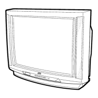
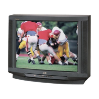
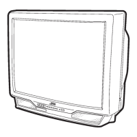
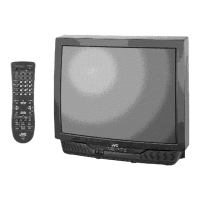
EasyManua.ls Logo

JVC AV-32D202/G - User Manual

JVC AV-32D202/G
84 pages
Print Icon
To Next Page IconTo Next Page
Loading...
SERVICE MANUAL
COLOR TELEVISION
BASIC CHASSIS
AC
No. 51799
Mar. 2001
COPYRIGHT © 2001 VICTOR COMPANY OF JAPAN, LTD.
TVTV
RM-C303G
[AV-32D202]
[AV-32D302]
RM-C301G
[AV-32D502]
AV-32D202
AV-32D302
AV-32D502
AV-32D202 /G AV-32D302 /G AV-32D502 /G
AV-32D202 /H AV-32D302 /H AV-32D502 /H
AV-32D202
/M AV-32D302 /M AV-32D502 /M
CONTENTS
a SPECIFICATIONS ....................................................................................................................................2
a SAFETY PRECAUTIONS ........................................................................................................................3
a FEATURES ..............................................................................................................................................4
a MAIN DIFFERENCE LIST........................................................................................................................5
a HOW TO IDENTIFY MODELS ..................................................................................................................5
a FUNCTIONS .............................................................................................................................................7
a SPECIFIC SERVICE INSTRUCTIONS ....................................................................................................8
a SERVICE ADJUSTMENTS ....................................................................................................................13
¤ STANDARD CIRCUIT DIAGRAM (APPENDIX) .................................................................................. 2-1
a PARTS LIST ...........................................................................................................................................35
Question and Answer IconNeed help?

Do you have a question about the JVC AV-32D202/G and is the answer not in the manual?

Overview

This document is a service manual for JVC Color Televisions, specifically models AV-32D202, AV-32D302, and AV-32D502, all sharing the BASIC CHASSIS AC. It provides comprehensive information for servicing, maintenance, and understanding the device's functionalities.

Function Description:

The JVC Color Televisions described in this manual are designed to provide high-quality visual and audio entertainment. Key features include:

  • Full-square CRT (cathode ray tube): Reproduces fine textured pictures in every detail, ensuring a clear and vibrant display.
  • I2C bus control: Utilizes single chip ICs for efficient and integrated control of various functions.
  • Built-in Twin Tuner system: Available for the AV-32D502 model, allowing for enhanced channel reception capabilities.
  • Built-in HYPER-SURROUND system: Provides an immersive audio experience.
  • Picture-In-Picture (PIP) function: Available for the AV-32D502 model, enabling the display of two video sources simultaneously.
  • 3 LINE DIGITAL COMB FILTER circuit: Improves picture quality by reducing artifacts and enhancing color separation.
  • Component input terminal: Allows for connecting devices that utilize Component Video Signals, optimizing video quality.
  • Audio Video input terminals: Supports S-input (x1) and V-input (x2) for AV-32D202 and AV-32D302 models, and S-input (x2) and V-input (x2) for the AV-32D502 model, offering versatile connectivity.
  • Variable audio output terminal: Provides flexibility in connecting external audio systems.
  • Closed-caption broadcasts: Enables viewing of closed captions for accessibility.
  • AV COMPU LINK EX terminal: Facilitates integration with other JVC components for system control.

Important Technical Specifications:

  • Dimensions (W x H x D): 33-7/8" x 27" x 21-5/8" / 85.9cm × 68.4cm × 54.8cm.
  • Mass: 114.4 lbs / 52.0 kg.
  • TV RF System: CCIR(M).
  • Color Sound System: NTSC, BTSC System (Multi Channel Sound).
  • TV Receiving Channels and Frequency:
    • VL Band: (02~06) 54MHz~88MHz
    • VH Band: (07~13) 174MHz~216MHz
    • UHF Band: (14~69) 470MHz~806MHz
  • CATV Receiving Channels and Frequency:
    • Low Band: (02~06, A-8) by (02~06&01)
    • High Band: (07~13) by (07~13)
    • Mid Band: (A~I) by (14~22)
    • Super Band: (J~W) by (23~36)
    • Hyper Band: (W+1~W+28) by (37~64)
    • Ultra Band: (W+29~W+84) by (65~125)
    • Sub Mid Band: (A8, A4~A1) by (01, 96~99)
    • Total Channels: 180 Channels (54MHz~804MHz).
  • Intermediate Frequency:
    • Video IF Carrier: 45.75MHz
    • Sound IF Carrier: 41.25MHz (4.5MHz)
    • Color Sub Carrier: 3.58MHz
  • Power Input: 120V AC, 60Hz.
  • Power Consumption: 128W [AV-32D202, AV-32D302], 133W [AV-32D502].
  • Picture Tube: 32" (80cm) Measured Diagonally.
  • High Voltage: 31kV±1.3kV (at zero beam current).
  • Speaker: 2" × 4-3/4" / 5 × 12cm Oval type × 2.
  • Audio Power Output: 4W x 2 [AV-32D202, AV-32D302], 5W × 2 [AV-32D502].
  • Video / Audio Input (1/2/3):
    • Video(1,3): 1Vp-p, 75Ω (RCA pin jack)
    • Audio(1,2,3): 500mVrms (-4dBs), High Impedance (RCA pin jack)
    • S-Video (Input 1 Over) [AV-32D202, AV-32D302], (Input 1/2 Over) [AV-32D502]
      • Y: 1Vp-p Positive (negative sync provided, when terminated with 75Ω)
      • C: 0.286Vp-p (burst signal, when terminated with 75Ω)
    • Component Input (Input 2):
      • Y: 1Vp-p positive (negative sync provided, when terminated with 75Ω)
      • PB/PR: 0.7Vp-p 75 Ω
  • Audio Output (Variable): More than 0~1550mVrms (+6dBs), Low impedance (400Hz when modulated 100%) (RCA pin jack).
  • AV Compu link EX Input: 3.5mm mini jack.
  • Antenna terminal: 75Ω (VHF/UHF) Terminal, F-Type Connector.
  • Remote Control Unit: RM-C303G-1A [AV-32D202, AV-32D302], RM-C301G-2A [AV-32D502] (AA/R6/UM-3 battery × 2).

Usage Features:

The televisions are operated via a front panel and a remote control unit.

  • Front Panel: Includes buttons for MENU, CHANNEL (+/-), VOLUME (+/-), POWER, and ON TIMER.
  • Front Panel Door Opened: Reveals INPUT3 VIDEO/AUDIO TERMINAL (VIDEO, L/MONO-AUDIO-R).
  • Rear Panel: Offers extensive connectivity options:
    • AUDIO (L/MONO, R) and VIDEO inputs.
    • S-VIDEO input (Input-1 Over for AV-32D202/AV-32D302; Input-1/2 Over for AV-32D502).
    • COMPONENT VIDEO inputs (Y, PB, PR).
    • AUDIO OUT (L/MONO, R).
    • AV COMPU LINK EX terminal.
    • 75Ω (VHF/UHF) antenna terminal.
  • Remote Control Unit (RM-C303G-1A for AV-32D202/AV-32D302, RM-C301G-2A for AV-32D502): Provides full control over TV functions, including power, input selection, channel and volume control, display options, sleep timer, surround sound, V-CHIP, and menu navigation. Specific buttons include TV/CATV, VCR/DVD, BBE, FREEZE, SWAP, 100+, RETURN, HYPER SURROUND, LIGHT, MUTING, PIP OFF, and VCR/DVD controls (REW, PLAY, FF, REC, STOP, PAUSE, OPEN/CLOSE, STILL/PAUSE).
  • Service Menu Operation: Accessible via a specific key sequence on the remote control (SLEEP TIMER, DISPLAY, VIDEO STATUS keys simultaneously), allowing access to various setting and adjustment modes for PICTURE, SOUND, THEATER, OTHERS, PIP (AV-32D502 only), LOW LIGHT, HIGH LIGHT, RF AFC, VCO(CW), and I2C BUS CTRL.

Maintenance Features:

The manual details specific service instructions and adjustments to ensure proper functioning and safety.

  • Disassembly Procedure: Step-by-step guide for removing the rear cover, speakers, chassis, terminal board, front control and front AV input PW boards, and LF PW board.
  • CRT Removal: Detailed instructions for safe removal and replacement of the CRT, emphasizing the need for two or more persons and the use of a CRT change table.
  • Silicon Grease Coating: Instructions for applying silicon grease for electrical insulation on the CRT anode cap section after replacement or repair.
  • Memory IC Replacement: Procedure for replacing the memory IC, including power off/on, initial value entry, and system constant check and setting via the service menu.
  • Service Adjustments: Comprehensive list of adjustments, including:
    • B1 POWER SUPPLY: Check and adjustment.
    • RF AGC: Adjustment to eliminate noise.
    • FOCUS: Adjustment for clear horizontal and vertical lines.
    • WHITE BALANCE (Low Light & High Light): Adjustment to achieve white screen.
    • PIP HIGH LIGHT WHITE BALANCE (AV-32D502 only): Adjustment for consistent brightness between main and PIP screens.
    • BRIGHT & SUB BRIGHT: Adjustment for optimum brightness.
    • CONTRAST & SUB CONTRAST: Adjustment for optimum contrast.
    • DEFLECTION: Adjustments for V CENTER, TRAPEZIUM, V-SIZE, V-LINEARITY, H SIZE, H POSITION, SIDE PIN, and CORNER PIN.
    • PIP DISPLAY POSITION (AV-32D502 only): Adjustment for PIP screen size.
    • CHROMA: Adjustments for SUB COLOR and SUB TINT.
    • MTS Circuit: Adjustments for INPUT LEVEL, STEREO VCO, SAP VCO, FILTER, and SEPARATION.
    • PURITY and CONVERGENCE: Adjustments for PURITY, STATIC CONVERGENCE, and DYNAMIC CONVERGENCE.
  • High Voltage Hold Down Circuit Check: Procedure to verify correct operation of the high voltage hold down circuit after repair.
  • Self Check Functions: Describes how the device detects malfunctions (e.g., over-current protector) and indicates them by turning off power and flashing the ON-TIMER LED.
  • Safety Precautions: Emphasizes the importance of using specified replacement parts, avoiding design alterations, using an isolation transformer when servicing hot chassis, and taking care with live/isolated ground connections to prevent shock or fire hazards. It also includes instructions for isolation and leakage current checks after re-assembly.

JVC AV-32D202/G Specifications

General IconGeneral
BrandJVC
ModelAV-32D202/G
CategoryTV
LanguageEnglish

Related product manuals