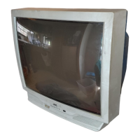
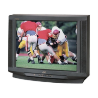
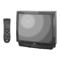
This document is a service manual for JVC Color Television models AV-32430 and AV-32432, including various sub-models denoted by suffixes like /M, /R, and /Y. It provides comprehensive information for servicing and maintaining these television sets.
Function Description
The JVC Color Television models AV-32430 and AV-32432 are designed to display video and audio signals from various sources. Key functions include:
- TV RF System: Capable of receiving VHF, UHF, and CATV signals, supporting multiple bands and channels.
- Color Sub Carrier: Processes color information at 3.58MHz.
- Picture Tube: Utilizes a 32-inch (80cm) measured diagonally picture tube with a 31kV±1.3kV (at zero beam current) high voltage. The speaker system consists of two 12cm (3-1/4" x 4-3/4") oval type speakers.
- Audio Power Output: Provides 3W + 3W audio output.
- Antenna Terminal: Features an F-type connector, 75ohm impedance for VHF/UHF.
- Video / Audio Input: Multiple input options including:
- Video 1 (1/3): 1V(p-p), 75ohm (RCA pin jack x 2)
- Audio 1 (2/3): 500mV(rms), (±4dBs), high impedance (RCA pin jack x 8)
- S-Video 1 (1/3): Y: 1V(p-p) positive (negative sync provided, when terminated with 75ohm), C: 0.286V(p-p) (burst signal when terminated with 75ohm)
- Component Video (2): RCA pin jack x 3
- S-Video (2): Y: 1V(p-p) positive (negative sync provided, when terminated with 75ohm), Pb/Pr: 0.7V(p-p) 75ohm
- Audio Output (Fix): Provides 500mV(rms), low impedance, (1kHz when modulated 100%) (RCA pin jack x 2).
- AV Compulink III: Facilitates 3.5mm mini jack x 1 connection.
- Remote Control Unit: Utilizes an RM-C203 (Lithium cell battery x 1) for convenient operation.
- Teletext (Closed Caption): Supports teletext broadcast of C1–C4 and T1–T4 formulas.
- Digital Comb Filter: Enhances picture quality by processing the refreshed image.
- Video Status: Displays the VIDEO STATUS function (STANDARD, DYNAMIC, SPORTS, GAME).
- V-Chip: Allows users to choose, view, and listen to a healthy program.
- Component Video Input Terminal: Connects to external devices with component video output.
- MTS Stereo System: Supports multi-channel TV sound system.
- EZ Surf: Provides channel ID and program name display.
- Return Plus: Allows programming a specific channel to return to while scanning through channels using CH+ and CH- buttons.
- On/Off & Sleep Timer: Enables automatic power on/off and sleep timer functions.
- Hyper Scan: Quickly scans for programs.
- Front Panel Lock: Locks the keys on the front of the TV to prevent accidental changes.
- Noise Muting: Suppresses blank blue screen over channels that are not broadcasting or are too weak.
Important Technical Specifications
- Dimensions (W x H x D): 76.8cm x 66.7cm x 54.7cm (30-1/4" x 26-1/4" x 21-1/2")
- Mass: 51.0kg (112.2 lbs)
- Intermediate Frequency: Video IF Carrier: 45.75MHz, Sound IF Carrier: 41.25MHz (4.5MHz)
- Power Input: AC 120V, 60Hz
- Power Consumption: 128W
- High Voltage: 31kV±1.3kV (at zero beam current)
- Speaker: 2 x 12cm (3-1/4" x 4-3/4") Oval type x 2
- Antenna Terminal: F-type connector, 75ohm
- Remote Control Unit: RM-C203 (Lithium cell battery x 1)
Usage Features
The television can be operated via the front control panel or the remote control unit.
Front Control Panel:
- Input: Selects video and audio inputs.
- Menu: Accesses the on-screen display (OSD) menu.
- Channel +/-: Changes channels.
- Volume +/-: Adjusts volume.
- Power: Turns the TV on/off.
- On Timer: Sets the on timer.
Remote Control Unit:
- Video Status: Displays video status.
- Power Button: Turns the TV on/off.
- Number Keys (0-9): Direct channel selection.
- Display: Shows on-screen information.
- Muting: Mutes/unmutes audio.
- Game/Sleep/C.C.: Accesses game mode, sleep timer, and closed caption functions.
- Menu: Accesses the OSD menu.
- Exit: Exits the current menu or function.
- VCR Control Keys: Controls connected VCRs.
- Channel +/-: Changes channels.
- Volume +/-: Adjusts volume.
Service Menu:
The service menu provides access to various adjustment items for technicians. To enter the service menu:
- Press the [SLEEP TIMER] key and set the SLEEP TIMER for "0 MIN".
- Then press the [DISPLAY] key and [VIDEO STATUS] key of the remote control unit at the same time to enter the SERVICE MENU screen.
Items in the service menu include:
- V.I/C(S): Adjusts VIDEO and CHROMA control circuit.
- DEF(D): Adjusts the DEFLECTION control circuit.
- SOUND(A): Adjusts the SOUND control circuit.
- OTHERS(F): Adjusts the display setting and other settings.
- LOW LIGHT: Adjusts the WHITE BALANCE (LOW LIGHT) control circuit.
- HIGH LIGHT: Adjusts the WHITE BALANCE (HIGH LIGHT) control circuit.
- VCO: Adjusts the VCO control circuit.
- I2C BUS: Adjusts the I2C BUS control circuit.
Maintenance Features
The manual provides detailed instructions for safety precautions, disassembly, and adjustment procedures.
Safety Precautions:
- Isolation Check: Perform an isolation check on exposed metal parts to prevent electrical shock.
- Dielectric Strength Test: Ensure proper insulation between the AC primary circuit and all metal parts.
- Leakage Current Check: Verify that the leakage current is within safe limits.
- Alternate Check Method: Use an isolation transformer and AC voltmeter to measure leakage current.
- High Voltage Hold Down Check: Verify the high voltage hold down circuit is operating correctly after repair.
- Isolation Transformer: Always use an isolation transformer when hot chassis.
- Component Replacement: Use only specified replacement parts to maintain safety and performance.
- X-Ray Emission: Be aware of X-ray emission from the CRT and associated components.
Disassembly Procedure:
- Removing the Rear Cover: Unplug the power plug, remove screws, and pull the rear cover toward you.
- Removing the Terminal Board: Remove screws and pull the terminal board.
- Removing the Main PWB: Remove screws and slide the chassis base backward along the chassis rail.
- Removing the Front Control PWB: Remove screws and pull the front control PWB.
- Removing the Speaker: Remove screws and pull the speaker.
- Checking the Main PWB: Pull out the chassis base and check the main PWB.
- Caution: Ensure no contact with other PWBs when removing.
- Wire Clamping and Cable Tying: Ensure wires are tied properly to prevent damage.
CRT Removal:
- Replacement of the CRT should be performed by 2 or more persons.
- Remove the rear cover and chassis.
- Put the CRT change table on soft cloth.
- While keeping the surface of the CRT down, mount the TV set on the CRT change table.
- Remove screws marked by arrows with a box type screwdriver.
- The CRT change table should be assembled according to the opposite sequence of its dismounting steps.
- The CRT change table should preferably be smaller than the CRT surface, and its height about 35cm.
Coating of Silicon Grease for Electrical Insulation on the CRT Anode Cap Section:
- Apply silicon grease to the anode cap section during replacement of the CRT and HV transformer.
Memory IC Replacement:
- This TV uses memory IC.
- In the memory IC, there are memorized data for correctly operating the video and deflection circuits.
- When replacing the memory IC, be sure to use IC written with the initial values of data.
- Procedure for Replacing Memory IC: Power off, unplug, replace IC, power on, set receive channels, and check user settings.
- Verify what to set in the SERVICE MENU, and set whatever is necessary.
Replacement of Chip Component:
- Cautions: Avoid heating for more than 3 seconds, do not rub the electrodes, and remove the chip part adequately. Do not reuse a chip part after removing it.
- Soldering Iron: Use a small tip soldering iron with a thin pointed end.
- Replacement Steps: Instructions for removing and installing chip parts, transistors, diodes, and variable resistors.
Adjustment Procedure:
- Adjustment Preparation: Use a remote control unit for adjustment. Ensure the TV has warmed up for at least 30 minutes before starting adjustments. Do not touch parts unless specified.
- Measuring Instrument and Fixtures: Requires a DC voltmeter, oscilloscope, frequency counter, signal generator (Pattern generator) [NTSC], audio multiplex signal generator, and remote control unit.
- Adjustment Locations: Diagrams show test points (TP) and adjustment locations for CRT socket PWB, front control PWB, front AV in PWB, and main PWB.
- Service Menu Items: Detailed description of each service menu item and its function.
- Setting Method: Instructions for adjusting service menu items using the remote control unit.
- Service Menu Flow Chart: Visual representation of the service menu structure.
- Initial Setting Value of Service Menu: Tables provide initial setting values for various parameters (e.g., BRIGHT, PICTURE, COLOR, TINT, DETAIL, R CUT OFF, G CUT OFF, B CUT OFF, R DRIVE, G DRIVE, B DRIVE, AFC GAIN, H POSI, V SIZE, V S CORR, V LIN, H SIZE, WVMT TOP, WVMT BTM, EWCR TOP, EWCR BTM, EW PARA, BLANK SW, IN LEVEL, FH MON, ST VCO, PIL CAN, FILTER, LOW SEP, HI SEP, SFH MON, SAP VCO, OSD POSI, CCD POSI, CCD FREQ, CCD CONT, PUR CONT, VNR CHK, VCSN TM, CCD PCHK, RED, GREEN, BLUE).
- Adjustment Procedure: Step-by-step instructions for checking and adjusting various components like DC power supply, IF VCO, RF AGC, FOCUS, DEFLECTION CIRCUIT (V. SIZE & V. CENTER, H. SIZE / H. CENTER / SIDEPIN), VIDEO CIRCUIT (WHITE BALANCE (LOW LIGHT), WHITE BALANCE (HIGH LIGHT), SUB BRIGHT, SUB CONTRAST, SUB COLOR, SUB TINT), and MTS CIRCUIT (MTS INPUT LEVEL check, MTS STEREO VCO, MTS SAP VCO, MTS FILTER, MTS SEPARATION).
This manual serves as a critical resource for technicians to ensure the proper functioning and longevity of the JVC Color Television models AV-32430 and AV-32432.