No. 51686
V-27D201
V-32D201
26
Item
Measuring
instrument
Test point Adjustment part Description
[ Method of adjustment without measuring instrument ]
DEMODULA-
TION RATIO
adjustment
Remote
control unit
No.31 DEMO RT BY
1. Receive the broadcast.
2. Select
No.31 DEMO RT BY
of the PICTURE MODE.
3. Set the initial setting value of the
No.31 DEMO RT BY
with
the LEFT/RIGHT key of the MENU.
4. If the blue color gain against the red color is not the best with
the initial setting value, make fine adjustment of the
No.31
DEMO RT BY
until you get the optimum gain.
"
DEMODULATION RATIO is the adjustment of the blue color
demodulation gain against the red color.
[ Method of adjustment using measuring instrument ]Signal
generator
Oscilloscope
Remote
control unit
TP-B
TP-E(#
##
#)
[CRT
SOCKET
PWB]
No.31 DEMO RT BY
1. Input the full field color bar signal (75% white).
2. Select
No.31 DEMO RT BY
of the PICTURE MODE.
3. Set the initial setting value of the
No.31 DEMO RT BY
with
the LEFT/RIGHT key of the MENU.
4. Connect the oscilloscope between
TP-B
and
TP-E
.
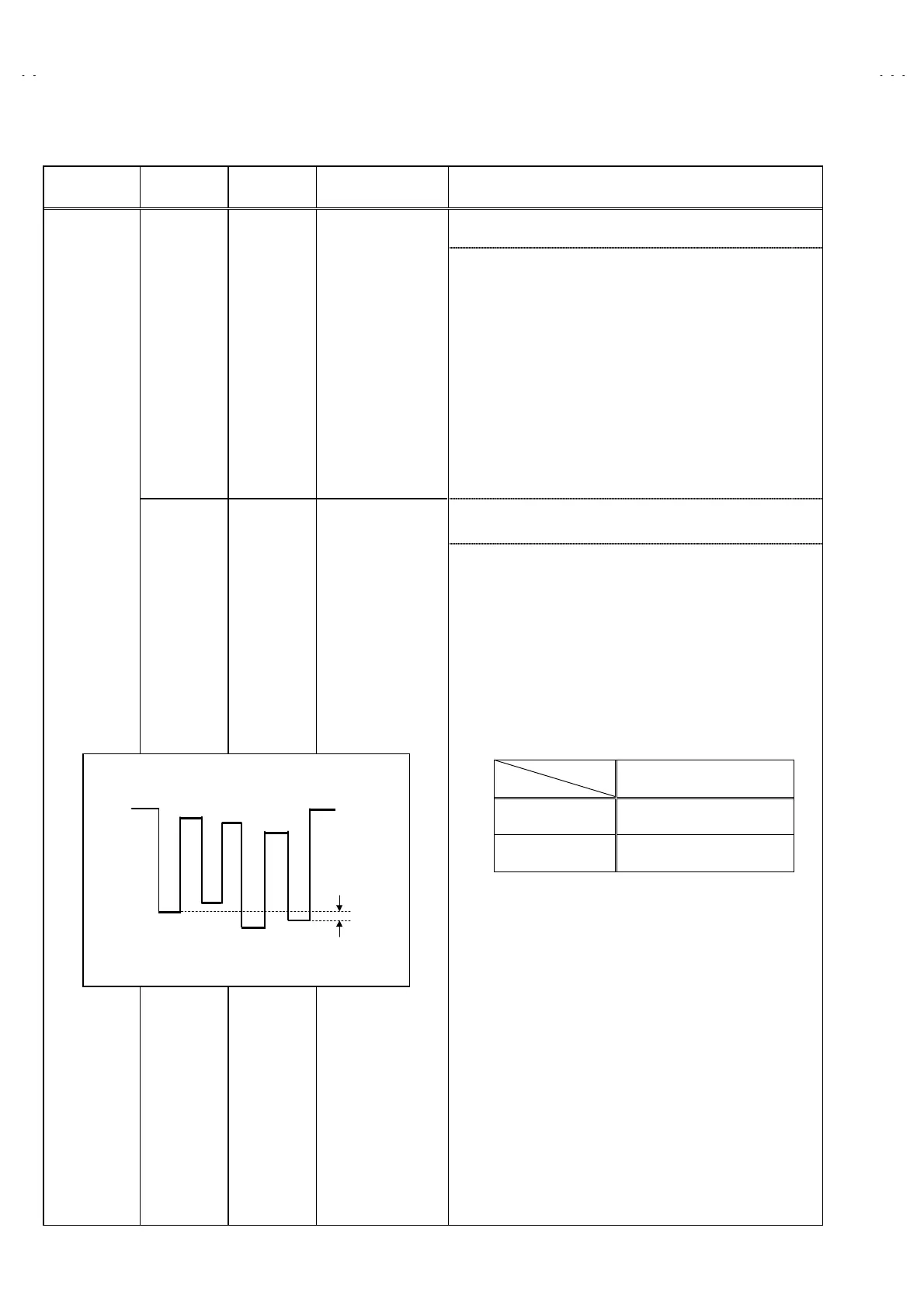
5. Adjust DEMODURATION RATIO and bring the value
of
(C)
in the illustration to the voltage shown in the table
bellow ( V
w-
B
).
(C)
W
Cy
G
Mg
B
R
Y
0V
Voltage between W-B
AV-27D201 +14V
AV-32D201 / A +18V