Do you have a question about the JVC FS-SD770R and is the answer not in the manual?
Procedure for performing isolation and leakage current tests for electrical safety.
Methods for grounding the workbench to protect against static discharge.
Precautions for handling the optical pickup to prevent ESD damage.
Guidelines for safely handling the sensitive traverse unit.
Procedure to remove the power amplifier board.
Procedure to remove the main circuit board.
Cleaning the laser pickup lens and identifying laser diode end-of-life symptoms.
Procedure for replacing the optical pickup and post-replacement operational checks.
Pin layout and block diagram for the UPD780024AGKB19 CPU.
Pin layout and block diagram for the MN662748RPM digital servo and signal processing IC.
Pin layout, block diagram, and pin functions for the AN22000A RF and servo amplifier IC.
| Type | Stereo System |
|---|---|
| CD Player | Yes |
| Radio Tuner | FM/AM |
| Bluetooth | No |
| USB Port | No |
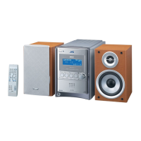
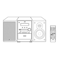
| Remote Control | Yes |
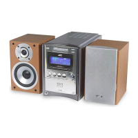
| Speaker Type | 2-way |
| Weight | 4.5 kg |
| Power Output | 30W |
| Functions | CD, Radio |
| CD Player Type | Single |
| Speaker Size | 10 cm |
| Speakers | Included |