50
WQERT
U
h
g
sadf
p
O
I
P
k
Y
j
SP
EP
PLAY
REC
A
B
C
D
E
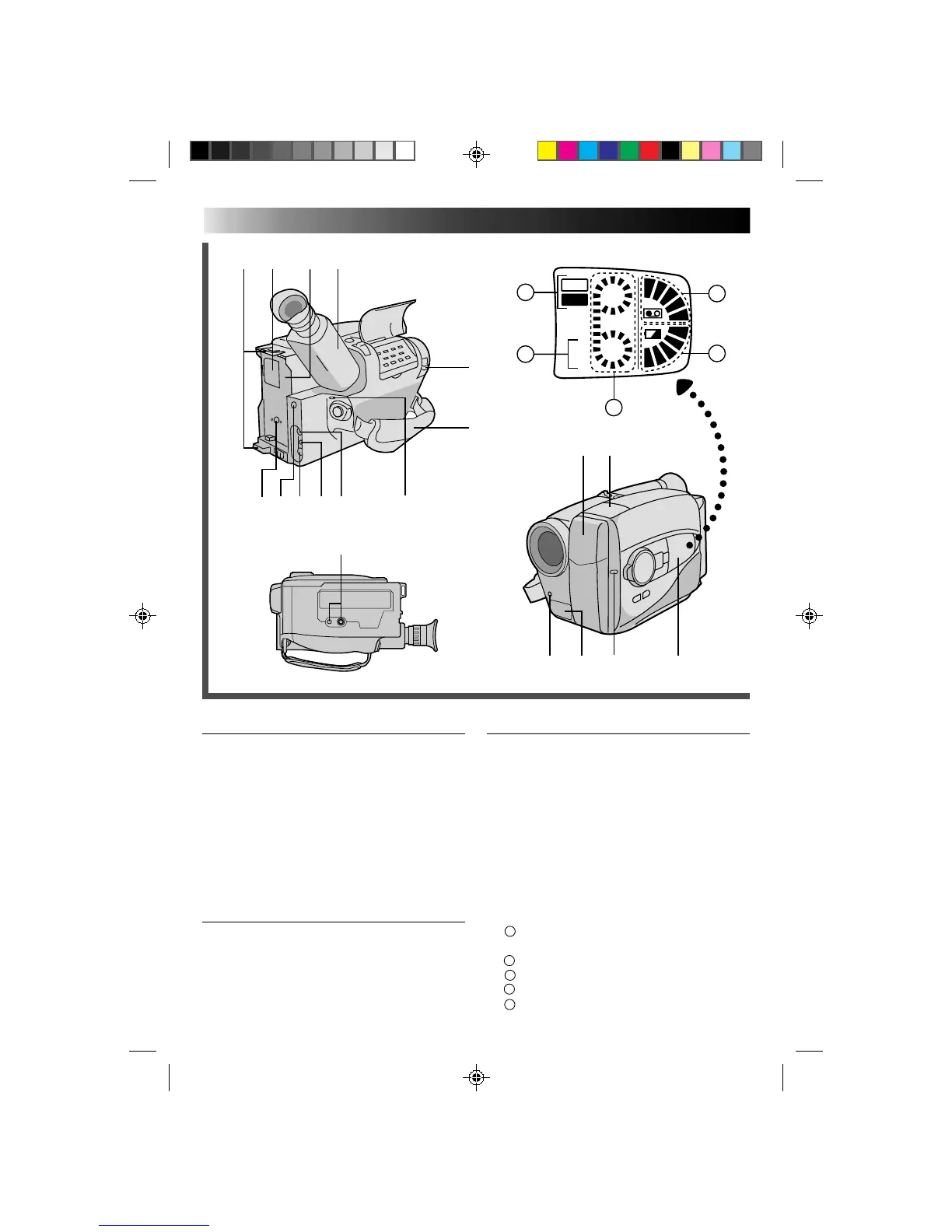
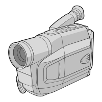
Connectors
p External MIC jack ................................ Z pg. 45
Q DC IN Jack ............................................ Z pg. 9
W JLIP (Joint Level Interface Protocol) Connector.
•Connect the Editing Cable when performing
Random Assemble Editing (Z pg. 42).
•In the future, it will be used to connect the
camcorder to a device such as a personal
computer.
E VIDEO Out Jack .................................. Z pg. 37
R RF DC OUT Jack .................................Z pg. 37
T AUDIO Out Jack .................................Z pg. 37
Indicators
Y Tally Lamp .......................................... Z pg. 16
U Power On Indicator............................. Z pg. 16
Other Parts
I Video Light .......................................... Z pg. 19
O Microphone ........................................ Z pg. 45
P Infrared beam sensor window ............. Z pg. 15
(Be careful not to cover this area; built-in
here is the sensor necessary for shooting.)
a Shoulder Strap Eyelets ......................... Z pg. 14
s Clock Battery Compartment ................ Z pg. 10
d Battery Pack Mount ...............................Z pg. 8
f Electronic Viewfinder .......................... Z pg. 10
g LENS COVER Switch ............................. Z pg. 5
h Grip Strap ........................................... Z pg. 14
j Tripod Mounting Socket ...................... Z pg. 14
k LCD window
A
Operating Mode (Playback//Recording)
Indicator
B
Recording Mode Indicator
C
Tape Running Indicator
D
Remaining Battery Power Inedicator
E
Tape Loaded/Remaining Tape Indicators


 To Next Page