EasyManua.ls Logo

JVC GR-D20EK

JVC GR-D20EK
46 pages
To Next Page IconTo Next Page
Loading...
SERVICE MANUAL
COPYRIGHT © 2003 VICTOR COMPANY OF JAPAN, LTD.
No.86730
2003/04
DIGITAL VIDEO CAMERA
86730200304
GR-D20EK,GR-D20E
X
,GR-D20E
Y
,GR-D20E
Z
,GR-D21EK,
GR-D40EK,GR-D40E
X
,GR-D40E
Y
,GR-D40E
Z
SPECIFICATION
Camcorder
General
Digital Video Camera
Connectors
AC Adapter
For disassembling and assembling of MECHANISM ASSEMBLY, refer to the SERVICE MANUAL No.86700 (MECHANISM ASSEMBLY).
PAL
Power supply : DC 11.0 V (Using AC Adapter)
DC 7.2 V (Using battery pack)
Power consumption
LCD monitor off, viewfinder on : Approx. 3.4 W
LCD monitor on, viewfinder off : Approx. 4.7 W
Dimensions (W x H x D) : 69 mm x 94 mm x 143 mm
(with the LCD monitor closed and the viewfinder pushed
back in)
Weight : Approx. 525 g
Operating temperature : 0°C to 40°C
Operating humidity : 35% to 80%
Storage temperature : -20°C to 50°C
Pickup : 1/6" CCD
Lens : F 1.6, f = 2.7 mm to 43.2 mm, 16:1 power zoom lens
Filter diameter : Ø37 mm
LCD monitor : 2.5" diagonally measured, LCD panel/TFT active
matrix system
Viewfinder : Electronic viewfinder with 0.24" black/white LCD
Speaker : Monaural
Format : DV format (SD mode)
Signal format : PAL standard
Recording/Playback format : Video: Digital component recording
: Audio: PCM digital recording,
32 kHz 4-channel (12-bit),
48 kHz 2-channel (16-bit)
Cassette : Mini DV cassette
Tape speed : SP : 18.8 mm/s
LP : 12.5 mm/s
Maximum recording time : SP : 80 min.
(using 80 min. cassette) LP : 120 min.
S-Video
Output : Y : 1 V (p-p), 75 , analogue
C : 0.29 V (p-p), 75 , analogue
Input* : Y : 0.8 V (p-p) -1.2 V (p-p), 75 , analogue
C : 0.2 V (p-p) -0.4 V (p-p), 75 , analogue
AV
Video output : 1 V (p-p), 75 , analogue
Video input* : 0.8 V (p-p) -1.2 V (p-p), 75 , analogue
Audio output : 300 mV (rms), 1 k, analogue, stereo
Audio input* : 300 mV (rms), 50 k, analogue, stereo
DV
Output : 4-pin, IEEE 1394 compliant
Input* : 4-pin, IEEE 1394 compliant
USB** :5-pin
EDIT Ø3.5 mm, 2-pole
* GR-D50/D30 only
** GR-D50/D40 only
Power requirement AC 110 V to 240 V ~, 50 Hz/60 Hz
Output : DC 11 V , 1 A
Specifications shown are for SP mode unless otherwise indicated. E & O.E. Design and specifications subject
to change without notice.
GR-D20EK,GR-D20EX,GR-D20EY,GR-D20EZ,GR-D21EK,GR-D40EK,GR-D40EX,GR-D40EY,GR-D40EZ M3D122,M3D124
Question and Answer IconNeed help?

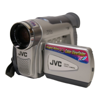
Do you have a question about the JVC GR-D20EK and is the answer not in the manual?

JVC GR-D20EK Specifications

General IconGeneral
Recording MediaMiniDV tape
Optical Zoom16x
Digital Zoom700x
LCD Screen2.5 inches
Image Sensor Size1/6 inch
Image Sensor TypeCCD
Video SignalPAL
InterfaceIEEE 1394 (FireWire)
TypeMiniDV
Image Sensor1/6-inch CCD
Effective Pixels680, 000
ViewfinderColor
Recording FormatDV

Summary

Product Specifications

General Specifications

Details on power supply, consumption, dimensions, weight, operating, and storage conditions.

Camcorder Specifications

Technical details regarding format, signal, recording, cassette, tape speed, and recording time.

Connectors and Ports

Information on various input and output connectors like S-Video, AV, and DV.

AC Adapter Specifications

Details on the power requirement and output of the AC adapter.

Cabinet Parts Assembly and Disassembly

2.2.1 Disassembly Flow Chart

Outlines the sequence for disassembling cabinet parts for servicing.

2.2.2 Disassembly Method

Lists parts and steps for the removal and assembly of cabinet components.

Camera Section and Board Assembly Procedures

2.3.1 Disassembly Flow Chart

Sequence for disassembling camera section and board assemblies.

2.3.2 Disassembly Method

Step-by-step guide for removing and assembling camera section boards.

Viewfinder (VF) Assembly Procedures

2.4.1 Disassembly of VF ASSEMBLY

Detailed steps for disassembling the Viewfinder (VF) assembly.

2.4.2 Disassembly of the LENS SA

Procedure for removing the Lens SA component from the VF assembly.

Monitor Assembly Disassembly

2.5.1 Disassembly of MONITOR ASSEMBLY (2.5 INCH)

Detailed steps for disassembling the 2.5-inch monitor assembly.

OP Block and CCD Board AssemblyDisassembly

2.6.1 Precautions

Handling guidelines for CCD Image Sensor and OP LPF.

2.6.2 Disassembly of CCD BOARD ASSEMBLY and CCD BASE ASSEMBLY

Steps for removing the CCD board and its base assembly.

2.6.3 Assembly of CCD BASE ASSEMBLY and CCD BOARD ASSEMBLY

Steps for assembling the CCD base and board assemblies.

2.6.4 Replacement of service repair parts

Guide for replacing specific service parts within the OP Block assembly.

Service Notes and Screw Management

Screw Management Chart

Chart detailing screw types, locations, and tightening torques.

Cassette Tape Ejection Procedure

Simplified Ejection Method

Simplified procedure for ejecting a cassette tape if normal ejection fails.

Emergency Display and Error Codes

Error Code Interpretation

Information on emergency display codes and their possible causes.

Adjustment Procedures

3.1 Preparation for Adjustment

Precautionary notes and list of required test equipment for adjustment.

3.2 Tools Required for Adjustment

A list of specialized tools necessary for performing adjustments.

Jig Connector Cable Information

3.3.1 Jig Connector Schematic Diagram

Diagram showing wiring before and after soldering for the jig connector.

3.3.2 Jig Connector Board

Illustration of the layout for the jig connector board.

Mechanism Compatibility Adjustment

3.4.1 Tape Pattern Check

Procedure to check tape patterns and adjust guide rollers for compatibility.

Electrical Adjustment Procedures

3.5.1 Electrical Adjustment with Personal Computer

Guidance on performing electrical adjustments using a personal computer.

Parts List

Packing and Accessory Parts

List of packing materials and accessories included with the product.

Mechanism Assembly Parts

List of parts for the mechanism assembly (M3).

Viewfinder Assembly Parts

List of parts for the electronic viewfinder assembly (M4).
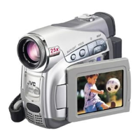
Related product manuals