(No.YF075)1-7
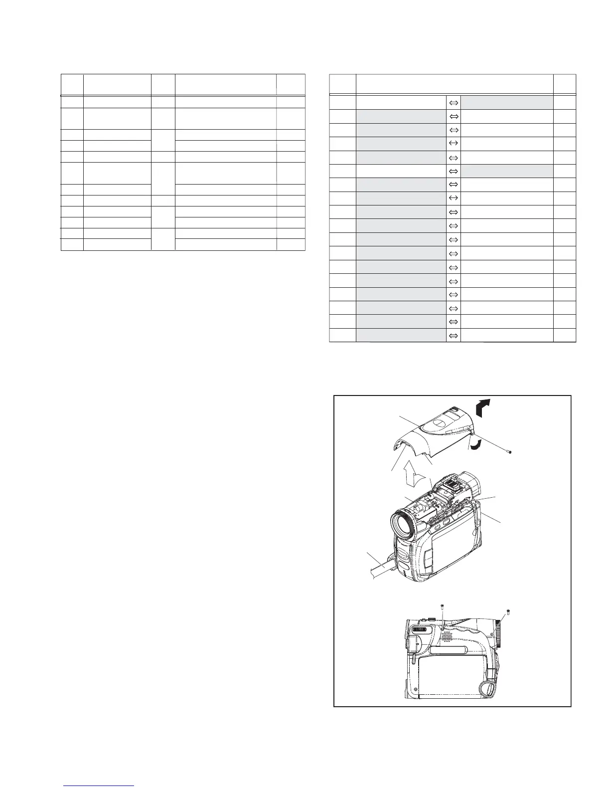
3.2.2 ASSEMBLY/DISASSEMBLY OF CABINET PARTS AND ELECTRICAL PARTS
zDisassembly procedure
NOTE1a:
During the procedure, remove the GRIP BELT.
NOTE1b:
Remove the screw (3) by pulling the COVER (SD) ASSY.
NOTE2a:
Remove the MONITOR ASSY by slightly lifting L2, with the
CASSETTE COVER open.
NOTE2b:
When attaching the MONITOR ASSY, be careful not to dam-
age the MONI SW.
NOTE4a:
Remove L4a by slightly lifting the REAR UNIT.
NOTE4b:
Be careful not to damage the connector.
NOTE4c:
When attaching the MONITOR ASSY, be careful not to dam-
age the EJECT SW.
Attach the MONITOR ASSY, with the CASSETTE COVER
closed.
NOTE10:
When attaching, firmly press the SHIELD COVER (PR) over
the FPC.
zDestination of connectors
Fig.FA1
STEP
No.
PART NAME
Fig.
No.
POINT NOTE
[1]
[2]
[3]
[4]
[5]
[6]
[7]
[8]
[9]
[10]
[11]
[12]
TOP COVER ASSY
MONITOR ASSY
VF ASSY
LOWER UNIT ASSY
REAR UNIT
FRONT COVER ASSY
OP BLOCK ASSY
MAIN BOARD ASSY
FRAME(Z27) ASSY
SIELD COVER(PR)
PRE/MDA BOARD ASSY
MECHA(B) ASSY
GRIP BELT,S1a,S1b,S1c,L1a,b,c,d,e,f
S2a,5(S2b),CASSETTE COVER,S2c,
S2d,L2,CN2
2(S3a),2(S3b),L3,CN3
S4a,S4b,L4a,b,CN4a,b
L5a,b,CN5a,b
S6,L6a,b,c,CN6a,b,2(S6b),PLATE(MIC),
MIC,L6e,d,FRONT BOARD ASSY
CN7a,CN7b
S8,L8a,b,CN8a,b
3(S9)
2(S10), L10
CN11a,b,c,d,e,f,2(S11)
-
FA1
FA2
FA3
FA4
FA5-1,2
FA6
FA7
FA8
NOTE1a,b
NOTE2a,b
-
NOTE4a,b,c
-
-
-
-
-
NOTE10
-
-
CN.NO.
CONNECTOR
PIN
NO.
CN2 OPE CN301 MAIN CN110 26
CN3 MAIN CN108 VF CN7001 16
CN4a MAIN CN109 ZOOM UNIT - 12
CN4b MAIN CN112 SPEAKER - 2
CN5a MAIN CN107 REAR UNIT - 40
CN5b MAIN CN111 SD CN901 12
CN6a MAIN CN103 FRONT CN701 17
CN6b MAIN CN114 INT MIC - 4
CN7a MAIN CN101 CCD - 20
CN7b MAIN CN102 OP BLOCK - 24
CN8a MAIN CN105 PRE/MDA CN408 40
CN8b MAIN CN104 PRE/MDA CN401 40
CN11a PRE/MDA CN406 SENSOR - 16
CN11b PRE/MDA CN405 CAPSTAN MOTOR - 18
CN11c PRE/MDA CN404 DRUM MOTOR - 11
CN11d PRE/MDA CN402 HEAD - 8
CN11e PRE/MDA CN407 ROTARY ENCODER SW - 6
CN11f PRE/MDA CN403 LOADING MOTOR - 6
GRIP BELT
[1]
1
(S1a)
2
(S1b)
3
(S1c)
COVER(SD) ASSY
L1f
L1b
L1a
L1d
L1c
L1e
NOTE1a
NOTE1b

 Loading...