(No.YF091)1-7
3.2.2 ASSEMBLY/DISASSEMBLY OF CABINET PARTS AND ELECTRICAL PARTS
zDisassembly procedure
NOTE1a:
During the procedure, leave the CASSETTE COVER (C.
COVER) open.
NOTE1b:
When removing the screw No.2, leave the JACK COVER
(DV) open. Be careful in handling the JACK COVER (DV),
as it comes off together when disassembling.
NOTE1c:
When removing the JACK COVER (DV), leave the VF AS-
SEMBLY pulled out.
NOTE4:
During the procedure, leave the CASSETTE COVER (C.
COVER) open.
NOTE5:
When removing the screw No.15, leave the JACK COVER
(DC) open.
NOTE6a:
During the procedure, be careful not to break the MAIN
BOARD parts.
NOTE6b:
When attaching the screw No.20, be careful not to damage
the FFC.
NOTE7:
When attaching, be careful with the wiring..
NOTE8:
During the procedure, leave the CASSETTE COVER (C.
COVER) open.
NOTE10a:
As the screw No.31 is located under the connector (CN10a),
pull out the connector first, before removing the screw.
NOTE10b:
During the procedure, be careful in handling the HEAT
SINK1.
NOTE10c:
When attaching, be careful with the wiring.
NOTE11a:
During the procedure, remove the GRIP BELT.
NOTE11b:
During the procedure, leave the CASSETTE COVER (C.
COVER) open.
NOTE11c:
When disassembling, be careful in handling the JACK COV-
ER (MIC) as it comes off together.
NOTE12:
During the procedure, be careful not to break the EJECT
SW.
NOTE13a:
During the procedure, be careful in handling the HEAT
SINK1.
NOTE13b:
Be careful with the wiring and the handling of the wire.
Pay special attention for the wire folding position.
NOTE15:
When attaching, be careful not to catch the FPC in between.
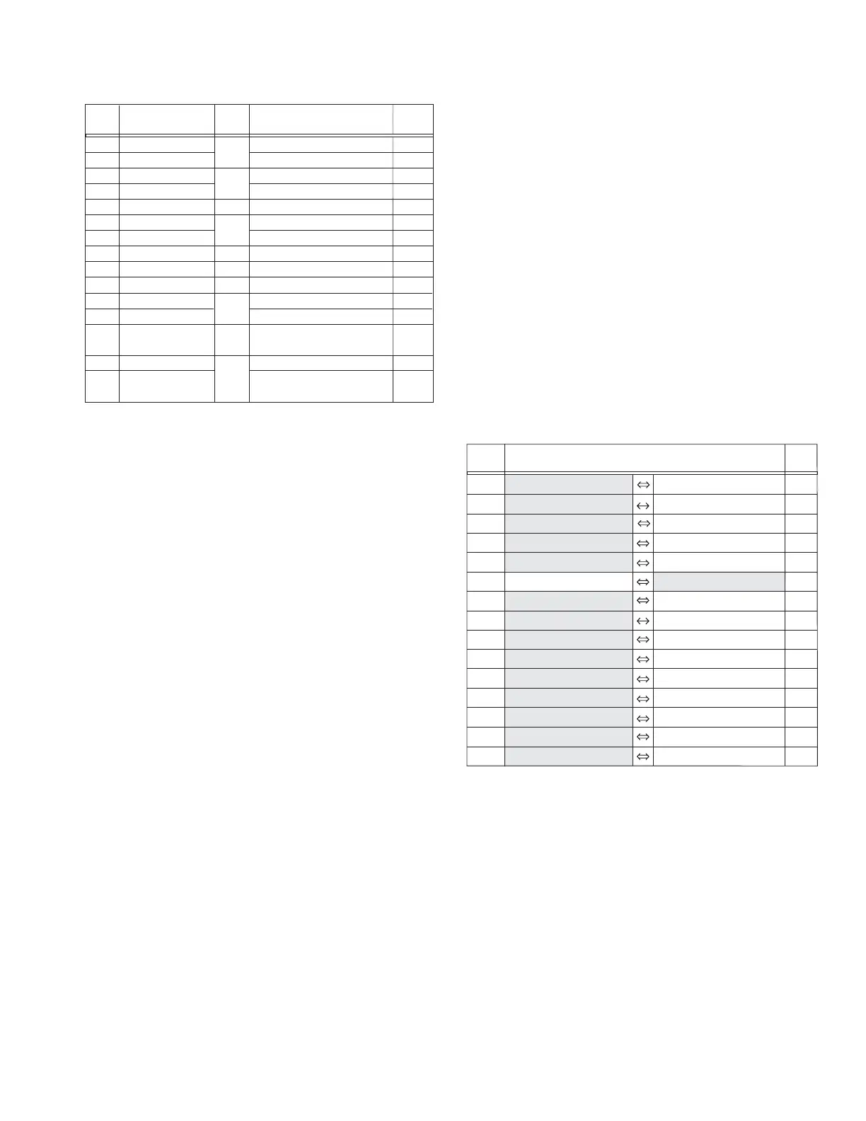
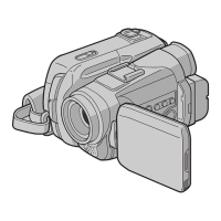
zDestination of connectors
[1]
[2]
[3]
[4]
[5]
[6]
[7]
[8]
[9]
[10]
[11]
[12]
[13]
[14]
[15]
COVER(JIG CON)
COVER(TOP) ASSY
SHOE
CENTER COVER
REAR COVER ASSY
FRONT COVER(N-MG)ASSY
MIC ASSY
UPPER CASE ASSY
OP FRAME ASSY
LOWER ASSY
COVER(FRONT) ASSY
FRONT BOARD ASSY
MAIN BOARD ASSY
MDA BOARD ASSY
MECHA(B) ASSY
S1a,S1b,JACK COVER(DV)
S2,L2
3(S3)
4(S4),L4
3(S5a),S5b,S5c,S5d,L5a,L5b,CN5
2(S6a),3(S6b),CN6
2(S7),
BKT(FRONT)
S8a,S8b,2(S8c),CN8,L8a,L8b
2(S9),CN9a,CN9b
CN10a,CN10b,CN10c,4(S10)
3(S11a),S11b,JACK COVER(MIC)
S12,L12a,L12b
3(S13a),2(L13a),
SHIELD PLATE,
CN13a,b,c,S13b
CN14a,b,c,d,2(S14)
S15a,
BKT(PRE-REC),
3(S15b),
BKT(MECHA) ASSY
FA1
FA2
FA3
FA4
FA5
FA6
FA7
FA8
FA9
FA10-1
FA10-2
NOTE1a,b,c
-
-
NOTE4
NOTE5
NOTE6a,b
NOTE7
NOTE8
-
NOTE10a,b,c
NOTE11a,b,c
NOTE12
NOTE13a,b
-
NOTE15
STEP
No.
PART
NOTE
Fig.
No.
POINT
CN5 MAIN CN103 REAR CN501 40
CN6 MAIN CN114 MIC - 4
CN8 MAIN CN105 MONI.OPE CN601 45
CN9a MAIN CN102 OP BLOCK - 22
CN9b MAIN CN101 CCD CN5001 20
CN10a MAIN CN107 FRONT CN401 16
CN10b MAIN CN108 CAMERA OPE - 14
CN10c MAIN CN112 SPEAKER - 2
CN13a MAIN CN104 MDA CN305 30
CN13b MAIN CN106 SENSOR - 16
CN13c MAIN CN109 HEAD - 8
CN14a MDA CN304 LOADING MOTOR - 6
CN14b MDA CN303
ROTARY ENCORDER SW
- 6
CN14c MDA CN302 DRUM MOTOR - 11
CN14d MDA CN301 CAPSTAN MOTOR - 18
CN.NO.
CONNECTOR
PIN
NO.