2-20
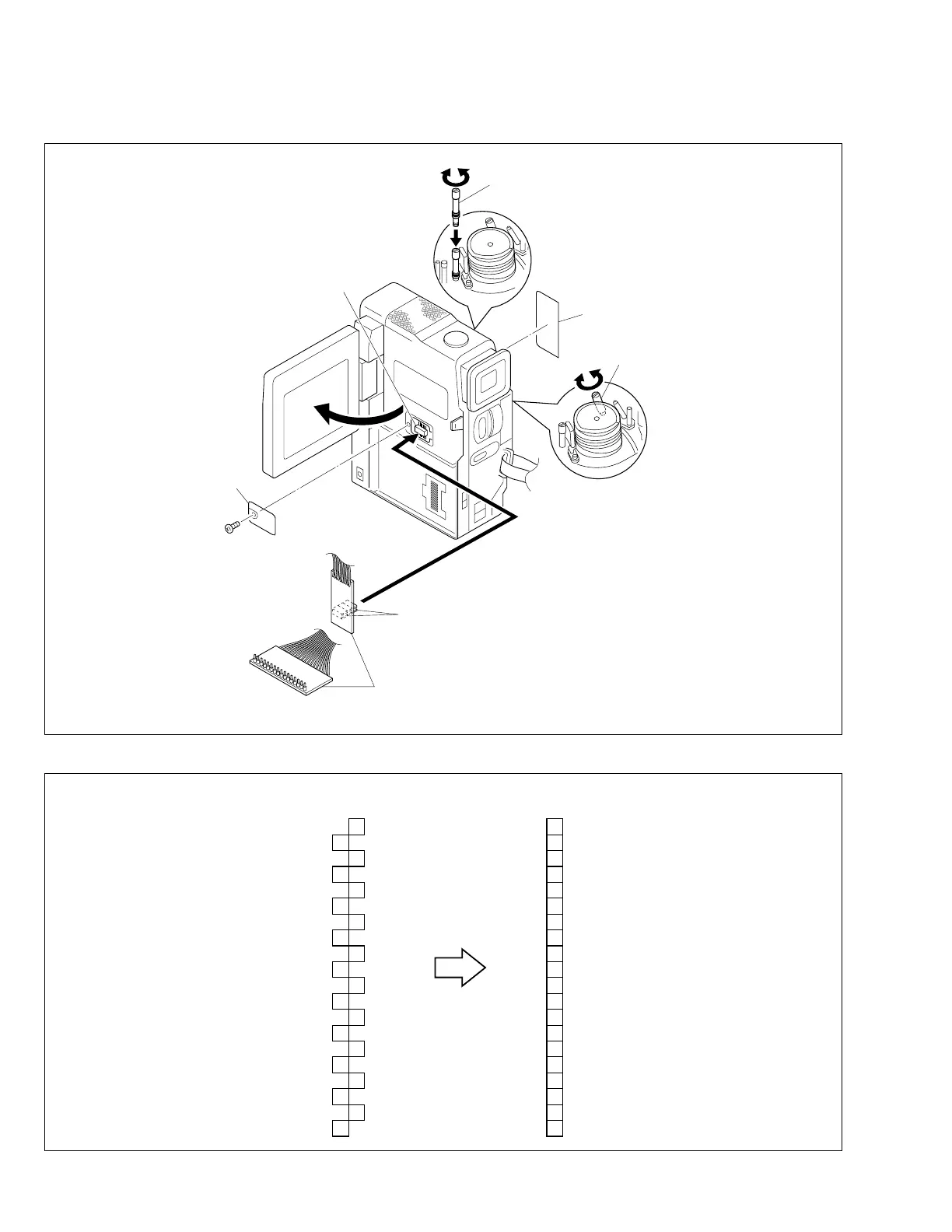
2.8 JIG CONNECTOR CABLE CONNECTION
Remove one screw (1) first and the cover (JIG) next.
Fig. 2-8-1 Jig connector cable connection
CN105
JIG CONNECTOR
CABLE
SHEET
GUIDE ROLLER (SUP) ASSY
GUIDE ROLLER
(TU) ASSY
EXTENSION
CONNECTOR
1
COVER
(JIG)
For supplying the power through the coupler by
removing the cover (for jig), use this extension
connector double for connecting the jig connector
cable.
NOTE)
Fig. 2-8-2 Jig connector cable schematic diagram
20 1AL_3VSYS
2
3
4
5
6
7
8
9
10
11
12
13
14
15
16
17
18
19
20
MAIN
CN105
JIG BOARD
(PIN NO.)
DJIG_SCK
10
19DJIG_SPT
CVF_G
9
18MON_G
JLIP_RX
8
17JLIP_TX
GND
7
16HID1
PB_CLK
6
15ENV_OUT
MAIN_VCO
5
14ATFI
FS_PLL
4
13I_MTR
IF_TX
3
12CJIG_RST
DJIG_MOD
2
11REG_3V
VPPC
AL_3VSYS
DJIG_SPT
MON_G
JLIP_TX
HID1
ENV_OUT
ATFI
I_MTR
CJIG_RST
REG_3V
DJIG_SCK
CVF_G
JLIP_RX
GND
PB_CLK
MAIN_VCO
FS_PLL
IF_TX
DJIG_MOD
VPPC
1
 Loading...