SERVICE MANUAL
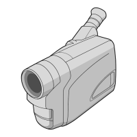
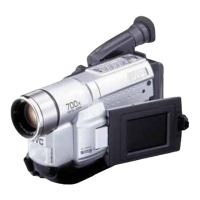
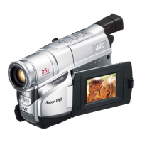
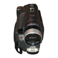
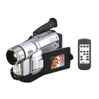
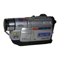
COMPACT VHS CAMCORDER
No. 86664
January 2002
This service manual is printed on 100% recycled paper.
COPYRIGHT © 2002 VICTOR COMPANY OF JAPAN, LTD.
GR-FXM383EG,SXM28EG,
SXM58EG,SXM780A
Regarding service information other than these sections, refer to the GR-FXM38EG, SXM48EG service manual (No. 86655).
Also, be sure to note important safety precautions provided in the service manual.
SPECIFICATIONS
(The specifications shown pertain specifically to the model GR-SXM78EA/SXM48EA/
SXM780A/SXM480A/SXM280A/SXM180A/SX140A)
VHS
PAL
625
Camcorder
General
Format : S-VHS/VHS PAL standard
Power source : DC 11 V
(Using AC Adapter)
DC 6 V (Using battery pack)
Power consumption
Viewfinder on : 4.0 W (GR-SXM78EA/SXM48EA/SXM780A/SXM480A/
SXM280A/SXM180A only)
3.7 W (GR-SX140A only)
LCD monitor* on : 4.5 W (GR-SXM78EA/SXM48EA/SXM780A/SXM480A/
SXM280A/SXM180A only)
Video light** : 3.0 W
* Applicable models only.
** GR-SXM78EA/SXM48EA/SXM780A/SXM480A/SXM280A only.
Signal system : PAL-type
Video recording system
Luminance : FM recording
Colour : Converted sub-carrier direct recording Conforms to VHS
standard
Cassette : / cassette
Tape speed
SP : 23.39 mm/sec.
LP : 11.70 mm/sec.
Recording time (max.)
SP : 60 minutes
LP : 120 minutes
(with EC-60 cassette)
Operating
temperature : 0°C to 40°C
Operating humidity : 35% to 80%
Storage temperature : –20°C to 50°C
Weight : Approx. 910 g (GR-SXM78EA/SXM48EA/SXM780A/SXM480A/
SXM280A only)
Approx. 900 g
(GR-SXM180A only)
Approx. 850 g (GR-SX140A only)
Dimensions : 200 mm x 112 mm x 118 mm
(W x H x D) (GR-SXM78EA/SXM48EA/SXM780A/SXM480A/SXM280A/
SXM180A only)
200 mm x 112 mm x 115 mm
(GR-SX140A only)
(with the LCD monitor* closed and with the viewfinder fully
tilted downward)
* Applicable models only.
Pickup : 1/6" format CCD
Lens : F1.6, f = 3.9 mm to 62.4 mm,
16:1 power zoom lens with auto iris and macro control, filter
diameter 40.5 mm
Viewfinder : Electronic viewfinder with 0.5" black/white CRT
White balance adjustment
: Auto/Manual adjustment
LCD monitor : 3" diagonally measured, LCD
(Applicable models only)
panel/TFT active matrix system
(GR-SXM78EA/SXM780A/SXM480A only)
2.5" diagonally measured, LCD panel/TFT active matrix system
(GR-SXM48EA/SXM280A/SXM180A only)
Speaker : Monaural
(Applicable models only)
Connectors
Video : 1 V (p-p
)
, 75 Ω unbalanced, analogue output (via Video output
connector)
Audio : 300 mV (rms), 1 kΩ analogue output
(via Audio output connector)
Digital : ø3.5 mm, 4-pole, mini-head jack
(GR-SXM78EA/SXM780A only)
S-Video : Y : 1 V (p-p
)
, 75 Ω, analogue
output
C : 0.30 V (p-p
)
, 75 Ω, analogue output
AC Adapter
Power requirement : AC 110 V — 240 V`, 50 Hz/60 Hz
Output : DC 11 V
, 1 A
Some accessories are not available in some areas. Please consult your nearest JVC
dealer for details on accessories and their availability.
Specifications shown are for SP mode unless otherwise indicated. E & O.E. Design and
specifications subject to change without notice.
Optional Accessories
• Battery Packs BN-V12U, BN-V20U, BN-V400U
• Compact S-VHS (
) Cassettes SE-C45/30
• Compact VHS (
) Cassettes EC-60/45/30
• Remote Control Unit RM-V700U
• Active Carrying Bag CB-V7U