Do you have a question about the JVC HR-J285EU and is the answer not in the manual?
Details on power, tape speed, format, and general operational parameters.
Technical details for audio input, output, frequency response, and noise.
Information on television system, recording format, and signal levels.
Guidelines and warnings for safe servicing procedures.
Procedures for testing insulation resistance and dielectric strength.
Guidelines for measuring clearance and leakage current.
Overview of IC control and system block diagram for short protection.
Explanation of MP KEY's role in EEPROM initialization.
Details on using remote control keys for EEPROM option setting.
General procedures for servicing the cabinet and main chassis.
Diagrams showing the breakdown of chassis and mechanism components.
Details on packing materials and included accessories.
Diagram indicating measurement and adjustment points in the electrical system.
Diagnostic steps for power supply unit (SMPS) issues.
Diagnostic steps for servo circuit problems.
Diagnostic steps for Y/C signal issues.
Diagnostic steps for tuner and IF circuit problems.
Diagnostic steps for Hi-Fi audio circuit issues.
Identifies individual parts of the deck mechanism via top and bottom view diagrams.
Procedures for disassembling the deck mechanism components, including drum, chassis, and drive train.
Procedures for adjusting and aligning the deck mechanism, including torque and alignment checks.
Diagnostic steps for common deck mechanism failures like auto REW and loading.
Diagnostic steps for issues with the front loading cassette mechanism.
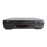
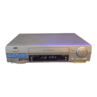
| Type | VCR |
|---|---|
| Video Format | VHS |
| Number of Heads | 4 |
| TV System | PAL |
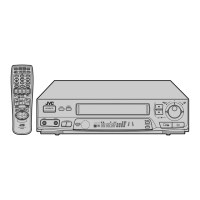
| Remote Control | Yes |
| Playback Speed | SP, LP |
| Recording Speed | SP, LP |
| Playback Features | Frame Advance |
| Inputs | Composite video, audio |
| Power Supply | AC 220-240V |